Binary inputs
CNT-SVX05B-EN 23
ON/CANCEL buttons on the zone sensor
Momentarily pressing the ON button on the zone sensor during unoccu-
pied mode places the controller in occupied bypass mode for 120 minutes.
You can adjust the number of minutes the Tracer AH540/541 is placed in
the occupied bypass mode by using the Rover service tool. The controller
remains in occupied bypass mode until the override time expires or until
you press the
CANCEL button on the zone sensor.
If the building automation system sends an unoccupied mode command to
the controller and
ON button on the zone sensor is pressed, the controller
goes to occupied bypass and communicates back to the building automa-
tion system that its effective occupancy mode is occupied bypass.
If the controller is in the unoccupied mode, regardless of the source (the
building automation system or a hard-wired occupancy binary input),
pressing the
ON button causes the controller to go into the occupied
bypass mode for the duration of the configured occupied bypass time.
Binary inputs
The Tracer AH540/541 controller has six binary inputs. Each binary
input associates an input signal of 0 Vdc with closed contacts and 24 Vdc
with open contacts. If the wired binary device has closed contacts, a mul-
timeter should measure less than 1.0 Vdc across the binary input termi-
nals. If the binary input has opened, a multimeter should measure
greater than 20 Vdc across the binary input terminals.
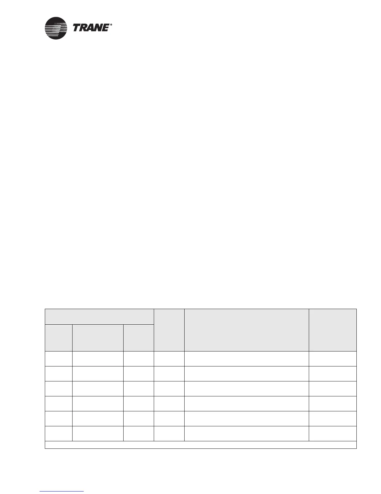
Table 7 describes the function of each of the binary inputs. For an expla-
nation of the diagnostics generated by each input, see “Diagnostics” on
page 89 For more information about how the functions of the controller
operate, see Chapter 4, “Sequence of operation.”
Table 7. Binary input functions and locations
AH540 AH541
Function Power function
Input
label
Terminal label
Factory
terminal
label
Field
terminal
label
IN 7 TB37-1 IN
TB37-2 GND
J37 IN7 Low-temperature detection or coil defrost 24 Vdc
ground
IN 8 TB38-1 IN
TB38-2 GND
J38 IN8 Run/stop 24 Vdc
ground
IN 9 TB39-1 IN
TB39-2 GND
J39 IN9
Occupancy or generic
1
24 Vdc
ground
IN 10 TB40-1 IN
TB40-2 GND
J40 IN10 Supply fan status 24 Vdc
ground
IN 11 TB41-1 IN
TB41-2 GND
J41 IN11 Filter status 24 Vdc
ground
IN 12 TB42-1 IN
TB42-2 GND
J42 IN12 Exhaust fan status or coil defrost 24 Vdc
ground
1 When configured as a generic binary input, it has no direct effect on controller operation.

 Loading...


