Analog inputs
CNT-SVX05B-EN 17
Analog inputs
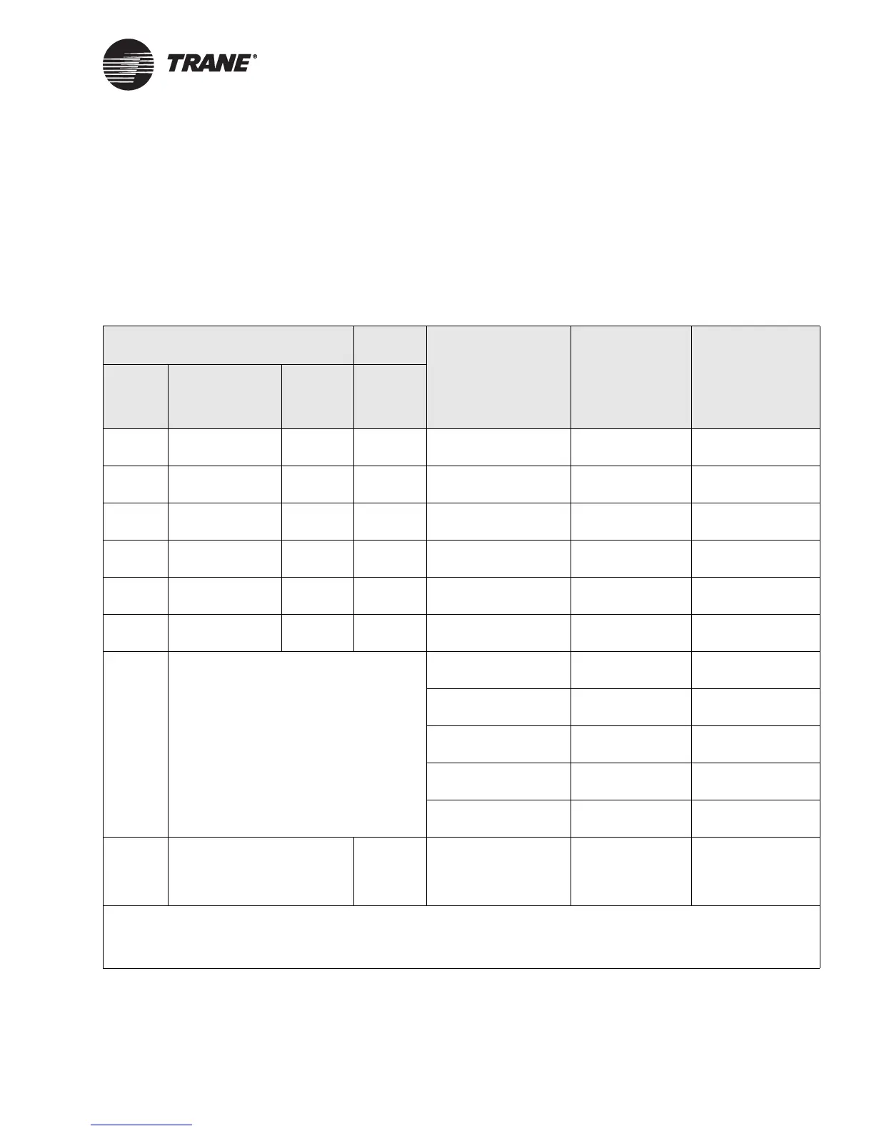
The Tracer AH540/541 controller has eight analog inputs. Table 5
describes the function of each of the analog inputs. Each function is
described in the following paragraphs. For an explanation of the diagnos-
tics generated by each input, see Chapter 6, “Verifying operation and
communication.” For more information about how the controller operates,
see Chapter 4, “Sequence of operation.”
Table 5. Analog input functions and locations
AH540 AH541
Function
Sensor type
1
Valid ranges
Input
label
Terminal label
Factory
terminal
label
Field
terminal
label
IN 1 TB31/1 IN
TB31/2 GND
J31 IN1 Space temperature 10 kΩ thermistor 5°F to 122°F
(-15°C to 50°C)
IN 2 TB32/1 IN
TB32/2 GND
J32 IN2 Local setpoint 1 kΩ
potentiometer
50°F to 85°F
(10°C to 29.4°C)
IN 3 TB33/1 IN
TB33/2 GND
J33 IN3
Fan mode switch
2
Switched
resistance
Off (4870 Ω ±5%)
Auto (2320 Ω ±5%)
IN 4 TB34/1 IN
TB34/2 GND
J34 IN4 Discharge air
temperature
10 kΩ thermistor –40°F to 212°F
(-40°C to 100°C)
IN 5 TB35/1 IN
TB35/2 GND
J35 IN5 Outdoor air
temperature
10 kΩ thermistor -40°F to 212°F
(-40°C to 100°C)
IN 6 TB36/1 IN
TB36/2 GND
J36 IN6 Mixed-air
temperature
RTD
3
-40°F to 212°F
(-40°C to 100°C)
IN 13
4
TB43 Space relative
humidity
Current:
4–20 mA
0 to 100%
CO
2
sensor Current:
4–20 mA
0 to 2000 ppm
Entering water
temperature
10 kΩ thermistor -40°F to 212°F
(-40°C to 100°C)
Evaporator refriger-
ant temperature
10 kΩ thermistor -40°F to 212°F
(-40°C to 100°C)
Generic temperature 10 kΩ thermistor -40°F to 212°F
(-40°C to 100°C)
Duct
static
J43 Duct
static
Duct static pressure Duct static-
pressure sensor
(Trane part num-
ber 4020 1159)
0 to 1250 Pa
0 to 5.02 in. water
1 See Appendix for analog input sensor curves (Table 73, Table 74, Table 75, Table 76, and Table 77).
2 Sensor type: Switched resistance fan auto = 2320
Ω, ±5%, fan off = 4870 Ω, ±5%.
3 Sensor type RTD averaging sensor, 1000
Ω at 0°C, platinum 385 curve.
4 This input is located on the main control board.

 Loading...


