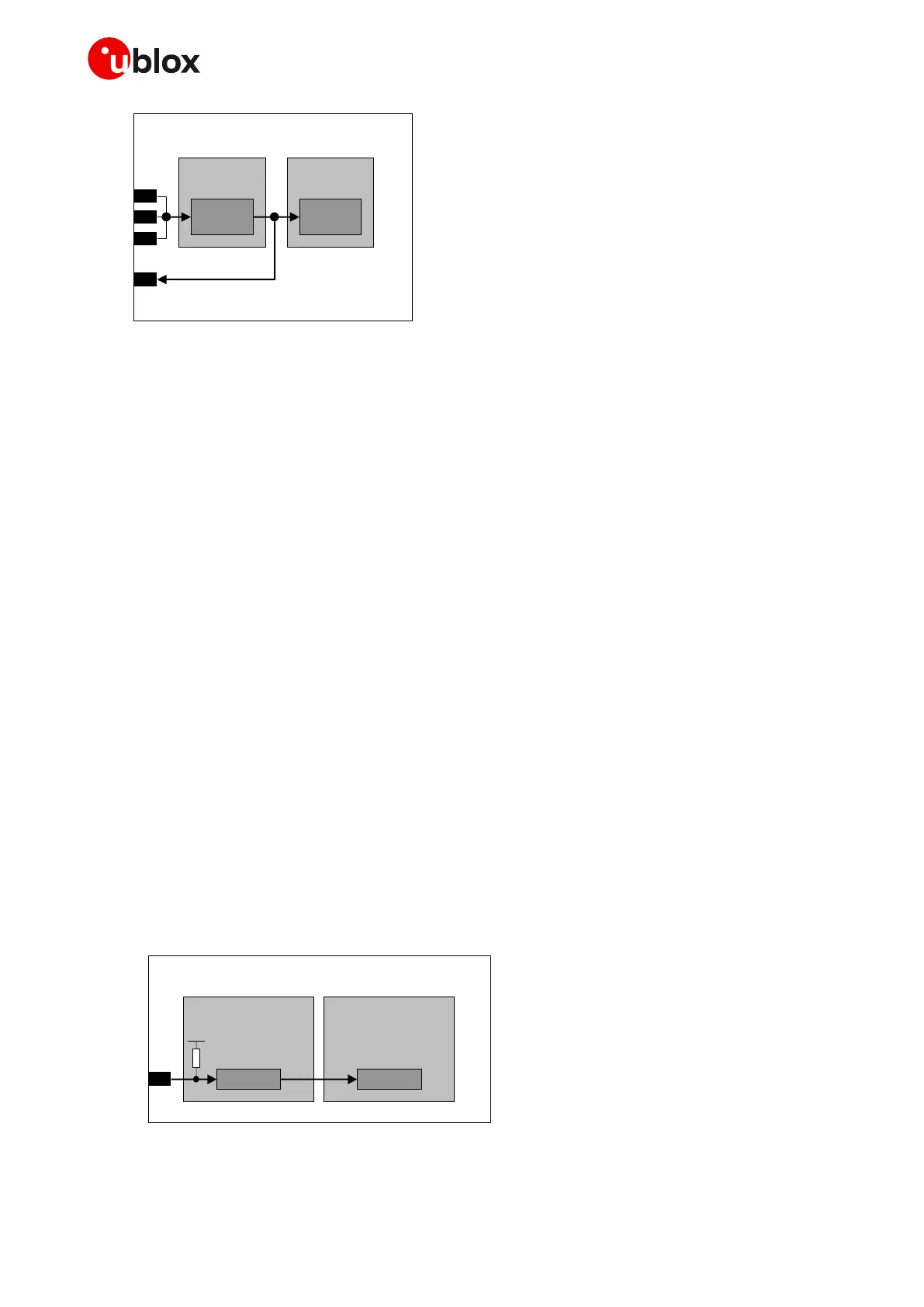
Figure 10: SARA-R5 series interfaces supply output (V_INT) simplified block diagram
1.6 System function interfaces
1.6.1 Module power-on
1.6.1.1 Switch-on events
When the SARA-R500S and SARA-R510M8S modules are in the not-powered mode (i.e. switched off,
with the VCC module supply not applied), the switch-on routine can be triggered by:
• Applying a voltage at the VCC module supply input within the operating range (see SARA-R5 series
data sheet [1]).
When the SARA-R510S modules are in the not-powered mode (i.e. switched off, with the VCC module
supply not applied), the switch-on routine can be triggered by:
• Applying a voltage at the VCC module supply input within the operating range, and then forcing a
low level at the PWR_ON input pin (normally high due to internal pull-up) for a valid time period (see
SARA-R5 series data sheet [1]).
When the SARA-R5 series modules are in the power-off mode (i.e. switched off, but with a valid voltage
present at the VCC module supply input) or in deep-sleep mode, they can be switched on or they can
be woken up as following:
• Forcing a low level at the PWR_ON input pin (normally high due to internal pull-up) for a valid time
period (see SARA-R5 series data sheet [1]).
As illustrated in Figure 11, the PWR_ON input pin is equipped with an internal pull-up resistor. Detailed
electrical characteristics with voltages and timings are described in the SARA-R5 series data
sheet [1].

 Loading...


