SARA-R5 series - System integration manual
UBX-19041356 - R04 Design-in Page 81 of 118
C1-Public
2.6 Data communication interfaces
2.6.1 UART interfaces
2.6.1.1 Guidelines for UART circuit design
Providing 1 UART with the full RS-232 functionality (using the complete V.24 link)
☞ Compatible with USIO variant 1; not compatible with USIO variants 0 / 2 / 3 / 4 (see section 1.9.1.1).
If RS-232 compatible signal levels are needed, two different external voltage translators (e.g. Maxim
MAX3237E and Texas Instruments SN74AVC4T774) can be used. The Texas Instruments chips
provide the translation from 1.8 V to 3.3 V, while the Maxim chip provides the translation from 3.3 V
to RS-232 compatible signal level.
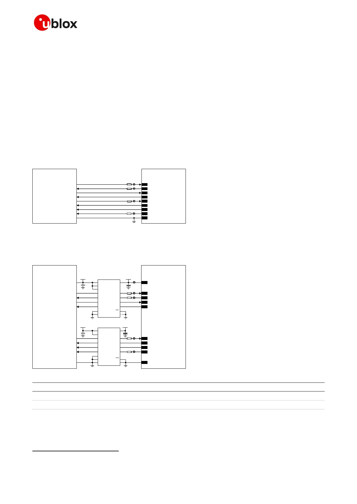
If a 1.8 V application processor (DTE) is used and complete RS-232 functionality is required, then the
complete 1.8 V UART of the module (DCE) should be connected to a 1.8 V DTE, as in Figure 54.
TxD
Application Processor
(1.8V DTE)
RxD
RTS
CTS
DTR
DSR
RI
DCD
GND
SARA-R5 series
(1.8V DCE)
12
TXD
9
DTR
13
RXD
10
RTS
11
CTS
6
DSR
7
RI
8
DCD
GND
0Ω
TP
0Ω
TP
0Ω
TP
0Ω
TP
Figure 54: 1 UART interface application circuit with complete V.24 link in DTE/DCE serial communication (1.8 V DTE)
If a 3.0 V application processor (DTE) is used, then it is recommended to connect the 1.8 V UART of
the module (DCE) by means of appropriate unidirectional voltage translators using the module V_INT
output as 1.8 V supply for the voltage translators on the module side, as described in Figure 55.
4
V_INT
TxD
Application Processor
(3.0V DTE)
RxD
RTS
CTS
DTR
DSR
RI
DCD
GND
SARA-R5 series
(1.8V DCE)
12
TXD
9
DTR
13
RXD
10
RTS
11
CTS
6
DSR
7
RI
8
DCD
GND
1V8
B1 A1
GND
U1
B3A3
VCCBVCCA
Unidirectional
voltage translator
C1
C2
3V0
DIR3
DIR2 OE
DIR1
VCC
B2 A2
B4A4
DIR4
1V8
B1 A1
GND
U2
B3A3
VCCBVCCA
Unidirectional
voltage translator
C3
C4
3V0
DIR1
DIR3 OE
B2 A2
B4A4
DIR4
DIR2
0Ω
TP
0Ω
TP
TP
0Ω
TP
0Ω
TP
Figure 55: 1 UART interface application circuit with complete V.24 link in DTE/DCE serial communication (3.0 V DTE)
Part number - Manufacturer
100 nF capacitor ceramic X7R 0402 10% 16 V
GCM155R71C104KA55 - Murata
Unidirectional voltage translator
SN74AVC4T774
6
- Texas Instruments
Table 36: Components for 1 UART application circuit with complete V.24 link in DTE/DCE serial communication (3.0 V DTE)
☞ Provide accessible test points directly connected to TXD and RXD pins for FW update purpose and
to DCD and DTR pins for diagnostic purpose.
Voltage translator providing partial power down feature, so the 3 V supply can be also ramped up before V_INT 1.8 V supply

 Loading...


