SARA-R5 series - System integration manual
UBX-19041356 - R04 Design-in Page 92 of 118
C1-Public
2.8 General purpose input / output (GPIO)
2.8.1 Guidelines for GPIO circuit design
A typical usage of SARA-R5 series modules’ GPIOs can be the following:
• Network indication provided over GPIO1 pin (see Figure 69 / Table 44 below)
• Module status / operating mode indication provided by a GPIO pin (see section 1.6.1)
• “External GNSS supply enable” function provided by the GPIO2 pin
(see section 2.6.5)
• “External GNSS data ready” function provided by the GPIO3 pin
13
(see section 2.6.5)
• “External GNSS time stamp” function provided by the GPIO4 pin
13
(see section 2.6.5)
• SIM card detection function provided over GPIO5 pin (see Figure 53 / Table 35 in section 2.5)
• Time pulse function provided over GPIO6 pin (see section Figure 69 / Table 44 below)
• Time stamp of external interrupt function provided over EXT_INT pin (see Figure 71)
• “External GNSS time pulse” function provided by the SDIO_CMD pin
13
(see section 2.6.5)
• Antenna dynamic tuning function provided over I2S_TXD and I2S_WA pins (see section 2.4.6)
SARA-R5 series
GPIO1
R1
R3
3V8
Network Indicator
R2
16
DL1
T1
SARA-R51 0M8S
GPIO6
Time Pulse
19
R1
R3
3V8
R2
DL1
T1
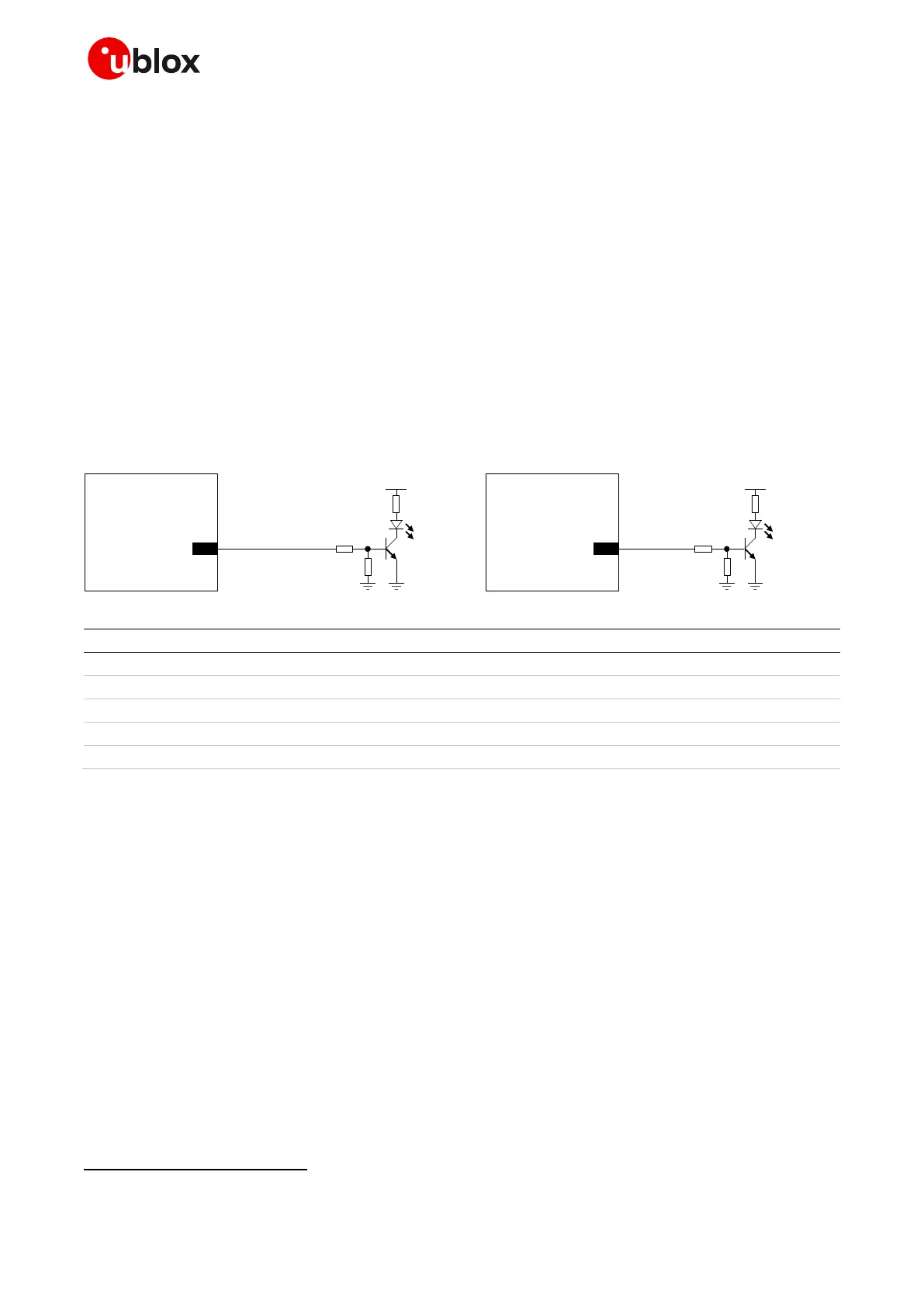
Figure 69: Application circuit for network indication provided over GPIO1
Table 44: Components for network indication application circuit
☞ Use transistors with at least an integrated resistor in the base pin or otherwise put a 10 k resistor
on the board in series to the GPIO of SARA-R5 series modules.
☞ Do not apply voltage to any GPIO of the module before the switch-on of the GPIOs supply (V_INT),
to avoid latch-up of circuits and allow a clean module boot. If the external signals connected to the
module cannot be tri-stated or set low, insert a multi-channel digital switch (e.g. TI
SN74CB3Q16244, TS5A3159, TS5A63157) between the two-circuit connections and set to high
impedance before V_INT switch-on.
☞ ESD sensitivity rating of the GPIO pins is 1 kV (Human Body Model according to JESD22-A114).
Higher protection level could be required if the lines are externally accessible and it can be achieved
by mounting an ESD protection (e.g. EPCOS CA05P4S14THSG varistor) close to accessible points.
☞ If the GPIO pins are not used, they can be left unconnected on the application board.
Not supported by SARA-R510M8S modules
Part number - Manufacturer
10 k resistor 0402 5% 0.1 W
47 k resistor 0402 5% 0.1 W
820 resistor 0402 5% 0.1 W
LTST-C190KRKT - Lite-on Technology Corporation

 Loading...


