SARA-R5 series - System integration manual
UBX-19041356 - R04 Design-in Page 65 of 118
C1-Public
2.4.3 GNSS antenna RF interface (ANT_GNSS)
☞ The GNSS antenna RF interface is not supported by SARA-R500S and SARA-R510S modules.
☞ For additional information and guidelines regarding the GNSS design, see the SARA-R5 series
positioning implementation application note [18].
The antenna and its placement are critical system factors for accurate GNSS reception. Use of a
ground plane will minimize the effects of ground reflections and enhance the antenna efficiency. A
good allowance for ground plane size is typically in the area of 50 x 50 to 70 x 70 mm
2
. The smaller the
electrical size of the plane, the narrower the reachable bandwidth and the lower the radiation
efficiency. Exercise care with rover vehicles that emit RF energy from motors etc. as interference may
extend into the GNSS band and couple into the GNSS antenna suppressing the wanted signal. For
more details about GNSS antennas see also the u-blox GNSS antennas application note [19].
Since SARA-R510M8S modules already include an internal SAW filter followed by an additional LNA
before the u-blox M8 GNSS chipset (as illustrated in Figure 4), they are optimized to work with passive
or active antennas without requiring additional external circuitry.
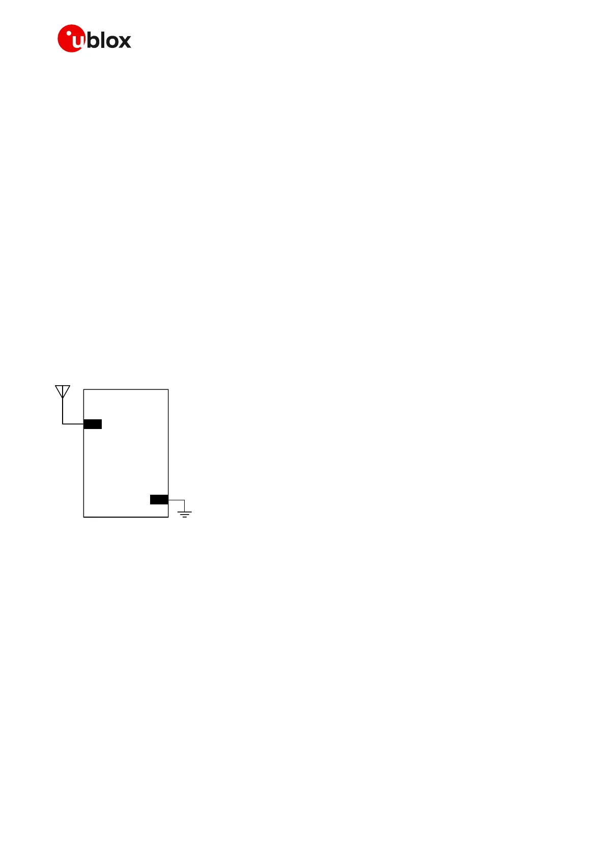
2.4.3.1 Guidelines for applications with a passive antenna
If a GNSS passive antenna with high gain and good sky view is used, together with a short 50 line
between antenna and receiver, and no jamming sources affect the GNSS passive antenna, the circuit
illustrated in Figure 42 can be used. This provides the minimum BoM cost and minimum board space.
Figure 42: Minimum circuit with GNSS passive antenna
If the connection between the module and antenna incurs additional losses (e.g. antenna placed far
away from the module, small ground plane for a patch antenna) or improved jamming immunity is
needed due to strong out-of-band jammers close to the GNSS antenna (e.g. the cellular antenna is
close to the GNSS antenna), consider adding an external SAW filter (see Table 22 for possible suitable
examples) close to the GNSS passive antenna, followed by an external LNA (see Table 23 for possible
suitable examples), as illustrated in Figure 43. Note that SARA-R510M8S modules already include an
internal SAW filter followed by an LNA before the u-blox M8 GNSS chipset (as illustrated in Figure 4),
so that additional external SAW and LNA are not required for most of the applications (see section
2.4.4 for further details and design-in guidelines regarding Cellular / GNSS RF coexistence).
☞ An external LNA with related external SAW filter are only required if the GNSS antenna is far away
(more than 10 cm) from the GNSS RF input of the module. In that case, the SAW and the LNA must
be placed close to the passive antenna.

 Loading...


