SARA-R5 series - System integration manual
UBX-19041356 - R04 Design-in Page 88 of 118
C1-Public
2.6.2 USB interface
☞ The USB interface is available for diagnostic purpose only.
2.6.2.1 Guidelines for USB circuit design
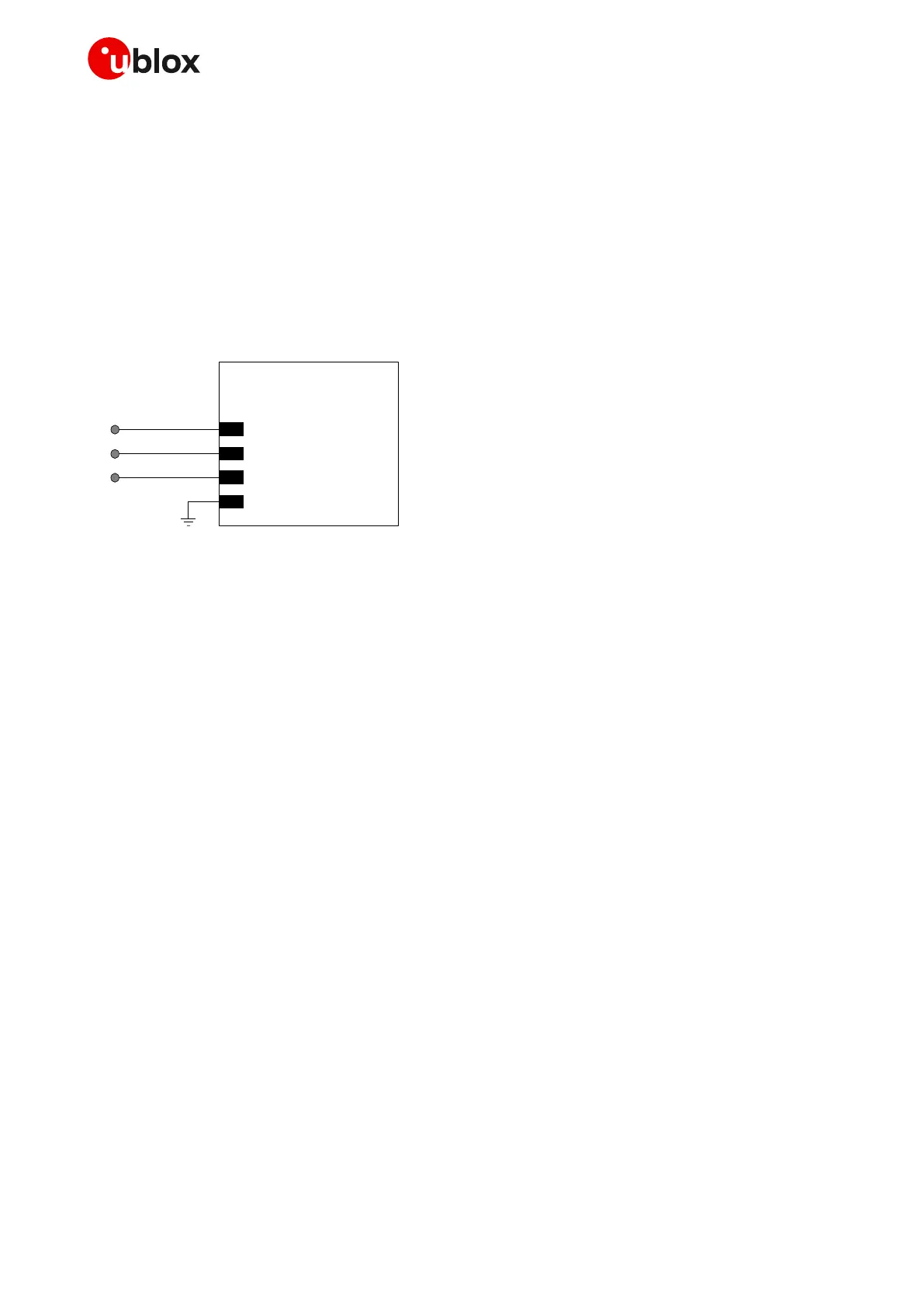
A suitable application circuit can be similar to the one illustrated in Figure 66, where direct external
access is provided for diagnostic purpose by means of test points made available on the application
board for VUSB_DET, USB_D+ and USB_D- lines.
USB pull-up or pull-down resistors and external series resistors on USB_D+ and USB_D- lines as
required by the USB 2.0 specification [4] are part of the module USB pins driver and do not need to be
externally provided.
Figure 66: SARA-R5 series modules USB application circuit providing access for diagnostic purpose
☞ It is highly recommended to provide accessible test points directly connected to the USB interface
pins (VUSB_DET, USB_D+, USB_D-) for diagnostic purpose.
☞ The USB interface pins ESD sensitivity rating is 1 kV (HBM according to JESD22-A114F). Higher
protection level could be required if the lines are externally accessible and it can be achieved by
mounting a very low capacitance (i.e. less or equal to 1 pF) ESD protection (e.g. the Littelfuse
PESD0402-140 ESD protection) on the lines connected to these pins, close to accessible points.
2.6.2.2 Guidelines for USB layout design
USB_D+ / USB_D- lines should be designed with differential characteristic impedance (Z
0
) as close as
possible to 90 and with common mode characteristic impedance (Z
CM
) as close as possible to 30
as defined by the USB 2.0 specification [4], routed as differential pair, with length as short as possible,
avoiding any stubs, and avoiding abrupt change of layout.
However, the USB interface is available for diagnostic purpose only, and therefore the layout is not
very critical: USB_D+ / USB_D- lines have to be routed as differential pair, with short length, up to the
related test points as illustrated in Figure 66.
2.6.3 SPI interfaces
☞ The SPI interfaces are not supported by the “00” product version of SARA-R5 series modules,
except for diagnostic purpose.
☞ Accessible test points directly connected to the SDIO_D0, SDIO_D1, SDIO_D2 and SDIO_D3 pins
may be provided for diagnostic purpose, alternatively to the highly recommended test points on
the USB interface pins.

 Loading...


