Table 42: Components for connecting SARA-R500S/SARA-R510S modules to a u-blox 1.8 V GNSS receiver
☞ For additional guidelines regarding cellular and GNSS RF coexistence, see section 2.4.4.
☞ For additional guidelines regarding the design of applications with u-blox 1.8 V GNSS receivers, see
the SARA-R5 series positioning implementation application note [18] and to the hardware
integration manual of the u-blox GNSS receivers.
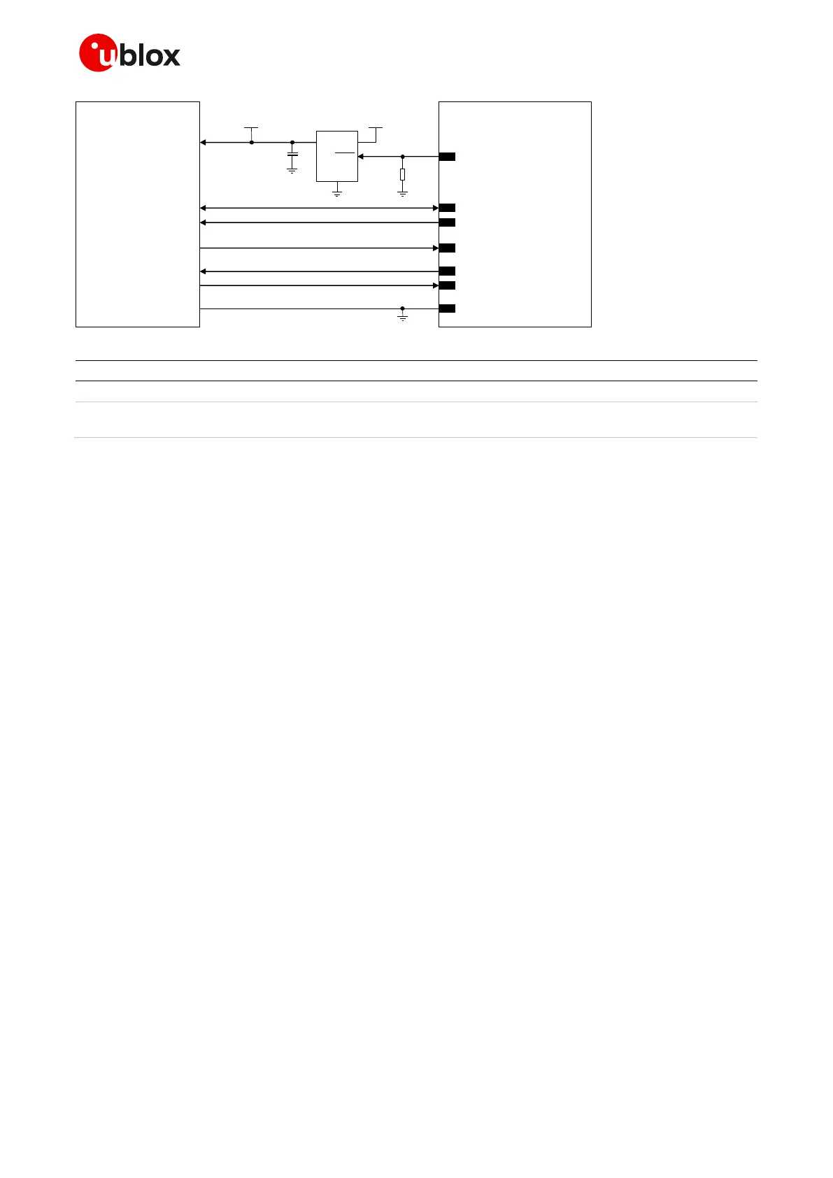
Connection with u-blox 3.0 V GNSS receivers
☞ Communication with an external GNSS receiver is not supported by SARA-R510M8S modules.
Figure 68 shows a circuit example for connecting the cellular module to a u-blox 3.0 V GNSS receiver:
• As the SDA and SCL pins of the cellular module are not tolerant up to 3.0 V, the connection to the
related I2C pins of the u-blox 3.0 V GNSS receiver must be provided using a suitable I2C-bus
bidirectional voltage translator (e.g. TI TCA9406, which additionally provides the partial power
down feature so that the GNSS 3.0 V supply can be ramped up before the V_INT 1.8 V cellular
supply). External pull-up resistors are not needed on the cellular module side, as they are already
integrated in the cellular module.
• The GPIO2 is connected to the active-high enable pin of the voltage regulator that supplies the
u-blox 3.0 V GNSS receiver providing the “GNSS supply enable” function (see section 1.11). An
additional pull-down resistor is provided to avoid a switch-on of the positioning receiver when the
cellular module is switched off or in the reset state.
• The GPIO3 pin is connected to the TXD1 pin of the u-blox 3.0 V GNSS receiver providing additional
“GNSS data ready” function profitable for power consumption optimization (see section 1.11), using
a suitable unidirectional general purpose voltage translator.
• The GPIO4 pin is connected to the EXTINT input pin of the u-blox 3.0 V GNSS receiver,
implementing the additional optional “External GNSS time stamp of external interrupt” function
for timing features (see section 1.11), using a suitable unidirectional general purpose voltage
translator.
• The SDIO_CMD pin is connected to the TIMEPULSE output pin of the u-blox 3.0 V GNSS receiver,
implementing the additional optional “External GNSS time pulse” function for timing features (see
section 1.11), using a suitable unidirectional general purpose voltage translator.

 Loading...


