Programable DC Electronic Load User Manual
17
Warning: Please make sure that the power supply voltage is consistent with the
supply voltage before turning on the power, otherwise the instrument will be burnt out.
Please be sure to connect the main power plug to a power socket with ground protection.
Do not use a wiring board without ground protection.
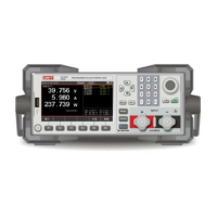
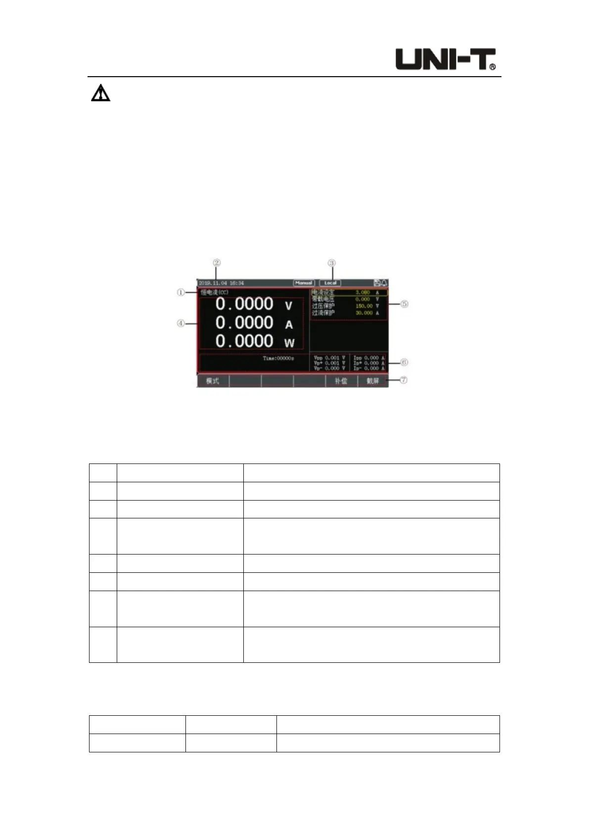
3.3 Introduction of Screen Display
After entering into the test mode, the LCD screen will be divided into several areas to
display different information.
Figure 3-2 Interface of Measurement
3.3.1 Display of Measurement Interface
No. Items Description
1 Mode Current measurement mode or status
2 Time Current system time
3 System icon
Display the status of U disk, remote compensation,
short-circuit test and trigger function
4 Parameters Real-time voltage, current and power
5 Set value Mode setting information, voltage and current value
6 Other parameters
Real-
time running time, other processes and result
data
7
Mode selection (soft
keyboard)
Select the work mode and operate the corresponding
functions at the bottom of the screen
3.3.2 Introduction of Status Bar
Status description Display Status Description
Measurement Status (Mode) Current measurement status or work mode
 Loading...