Programable DC Electronic Load User Manual
34
truly simulated, so that the test voltage and current are between a normal and stable value,
avoiding oscillations and other unstable conditions produced by constant resistor
discharge, so as to better check the actual loading of the LED drive power supply.
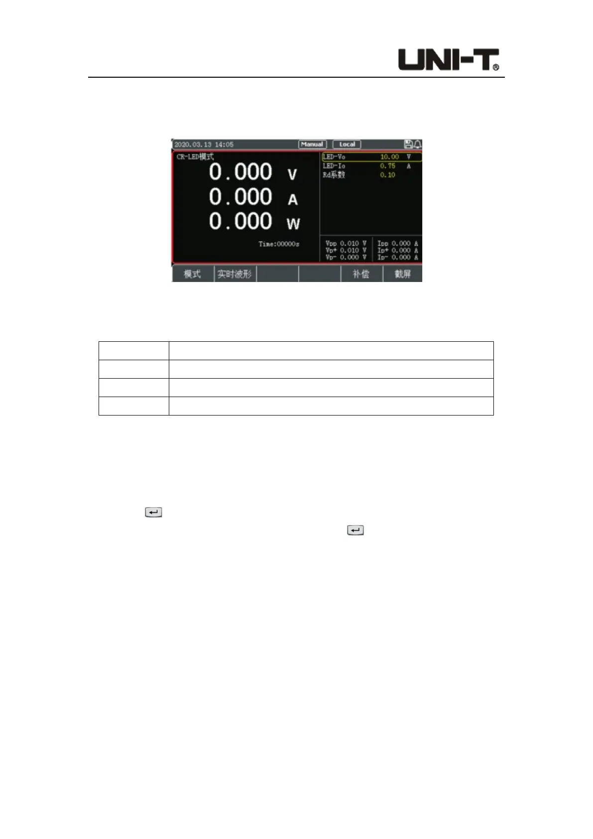
Figure 4-2-5-1 Interface of CR-LED Mode
Parameter setting in CR-LED mode:
Parameter Description
LED-Vo The operating voltage at the rated current of the LED power supply
LED-Io Rated output current of LED power supply
Rd Coeff Rd coefficient of the LED (setting range: 0.1~0.4)
Operation steps:
1. In initial interface, select [Mode], [More], and then press [CR-LED] to enter the setting
interface.
2. Move the cursor to the needed setting position by pulse knob, and press the Enter
button to change the parameter (the parameter changes from yellow to white)
by keyboard or pulse knob. Press the Enter button again to confirm. At this time,
the set value changes from white to yellow.
3. Other parameters can be modified in a similar way.
4. Press the ON button, the electronic load starts to load, and the indicator light below
the button lights up. If users need to stop the load, press the ON button again, and the
running indicator light goes out.
4.2.6 Battery Mode
Battery mode is used to detect the battery capacity. Battery capacity is an important
indicator of the battery which reflects battery life and reliability. The voltage will decrease
as the discharge time increases when testing the battery capacity, so the stop voltage
should be set. When the stop voltage is reached, the test ends. Users can click and view
 Loading...