Programable DC Electronic Load User Manual
68
display on the screen.
Operation steps:
1. Press the [System] key to enter SYSTEM CONFIG interface, and select [Local] at the
bottom of the screen to switch the current Local mode to Remote mode. The
"Remote" icon will be displayed at the top of the screen, indicating that the electronic
load is in Remote mode.
2. If users want to return to Local mode, just press the [Local] function key. At this time,
the word "Local" will be displayed at the top of the screen, indicating that the electronic
load is in Local mode.
3. Repeat step 1 to enter Remote mode again.
7. Communication Interface and Terminal
● RS-232C Communication
● Introduction of Terminal
7.1 RS-232C
UTL8500X series electronic load is equipped with RS-232C communication interface
according to standards. Users can use the corresponding communication lead for remote
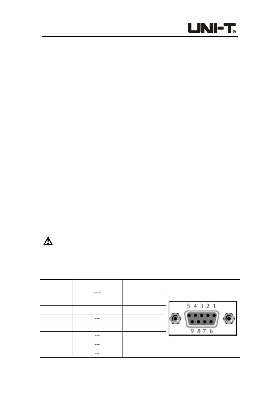
operation if they need. There is a DB9 female interface at the end of the electronic load,
which can be connected to the computer COM port by using a standard RS-232C cable.
Note: In actual use, the electronic load only uses three pins (2, 3 and 5) to
communicate with the device. It is recommended to turn off the power of the instrument
when plugging or unplugging the connector to avoid electrical shock.
Table 7-1 Definition of COM Interface (RS-232C) Pins
Pin number Symbol Description
1
/
2 TXD Transmit data
3 RXD Receive data
4 /
5 GND Ground
6 /
7 /
8 /
RS-232C connector
 Loading...