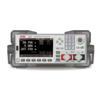
Programable DC Electronic Load User Manual
43
4.5 Trigger Method
When using Dynamic, List or Time mode, the trigger function of the electronic load may be
used. Users can choose manual trigger (Manual) or external trigger (External).
Operation steps:
1. In the Dynamic, List or Time mode page, users can quickly modify the trigger mode
by selecting [Trigger] through the function keys at the bottom of the screen, and the
words "Manual" or "External" will appear at the top of the screen;
2. When the external trigger is selected, the trigger signal is connected through the
trigger terminal on the rear panel to control every action of the electronic load;
3. When the manual trigger is selected, use the [Trig] button on the panel to trigger.
Each time users press [Trig] button, a corresponding trigger operation will be
executed.
4.6 Sense
When the electronic load is loaded with a relatively large current, it will produce a large
voltage drop on the connection lead between the load and the measured object. In order
to ensure the measurement accuracy, the electronic load has a pair of remote
measurement terminals on the rear panel. Through the terminals, users can have a
sampling measurement on the precise voltage at the output terminal of the instrument
under test.
Operation steps:
1. On each test mode page, select [Sense] via the function key at the bottom of the
screen. When the "Sense" icon appears at the top of the screen, it means that the
remote sense function has been turned on. At this time, the remote sampling voltage
measured on the back terminal is the actual voltage detected.
2. Press the function key [Sense] again to turn off the remote sense function. At this
time, the voltage measured on the main terminal on the front panel is the actual
voltage detected.
Note: When wiring, be sure to connect the object under test and the positive and
negative poles of the terminals correctly; the Sense switch cannot be switched in the
running state.
4.7 Screenshot
After inserting the U disk in the front panel, the electronic load will automatically recognize
 Loading...