Programable DC Electronic Load User Manual
40
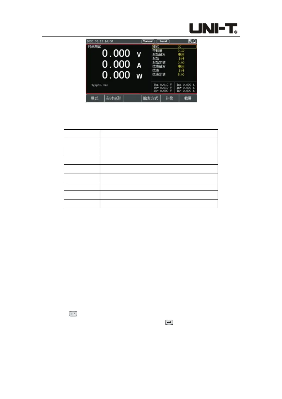
Figure 4-2-10-1 Interface of Time Mode
Parameter setting in time mode:
Parameter Description
Mode Set the load mode (CC/CV/CR/CP/Open)
Value Set the load value of the current mode
Start trigger Set the start condition (voltage/current/external)
End trigger Set the end condition (voltage/current/external)
Start edge Start trigger mode: Rise/Fall
End edge End trigger mode: Rise/Fall
Start value Set the start trigger value
End value Set the end trigger value
First set the loading mode and loading value, then set the start and end conditions and
trigger mode, and then set the start and end values. After the time test starts, the
electronic load is loaded according to the set mode and value. When the load captures
that the initial trigger condition is met, it starts timing; after running to the end trigger
condition, the load ends timing and the time measured is displayed on the screen.
The time mode simulates the test of the rising voltage speed of the oscilloscope, and can
be widely used in the field of startup time test of switch and power supply.
Operation steps:
1. In initial interface, select [Mode], [More], [More], and then press [Time] to enter the
setting interface.
2. Move the cursor to the needed setting position by pulse knob, and press the Enter
button to change the parameter (the parameter changes from yellow to white)
by keyboard or pulse knob. Press the Enter button again to confirm. At this time,
the set value changes from white to yellow.
3. Other parameters can be modified in a similar way.
4. Press the ON button, the electronic load starts to load, and the indicator light below
the button lights up. If users need to stop the load, press the ON button again, and the
 Loading...