Programable DC Electronic Load User Manual
70
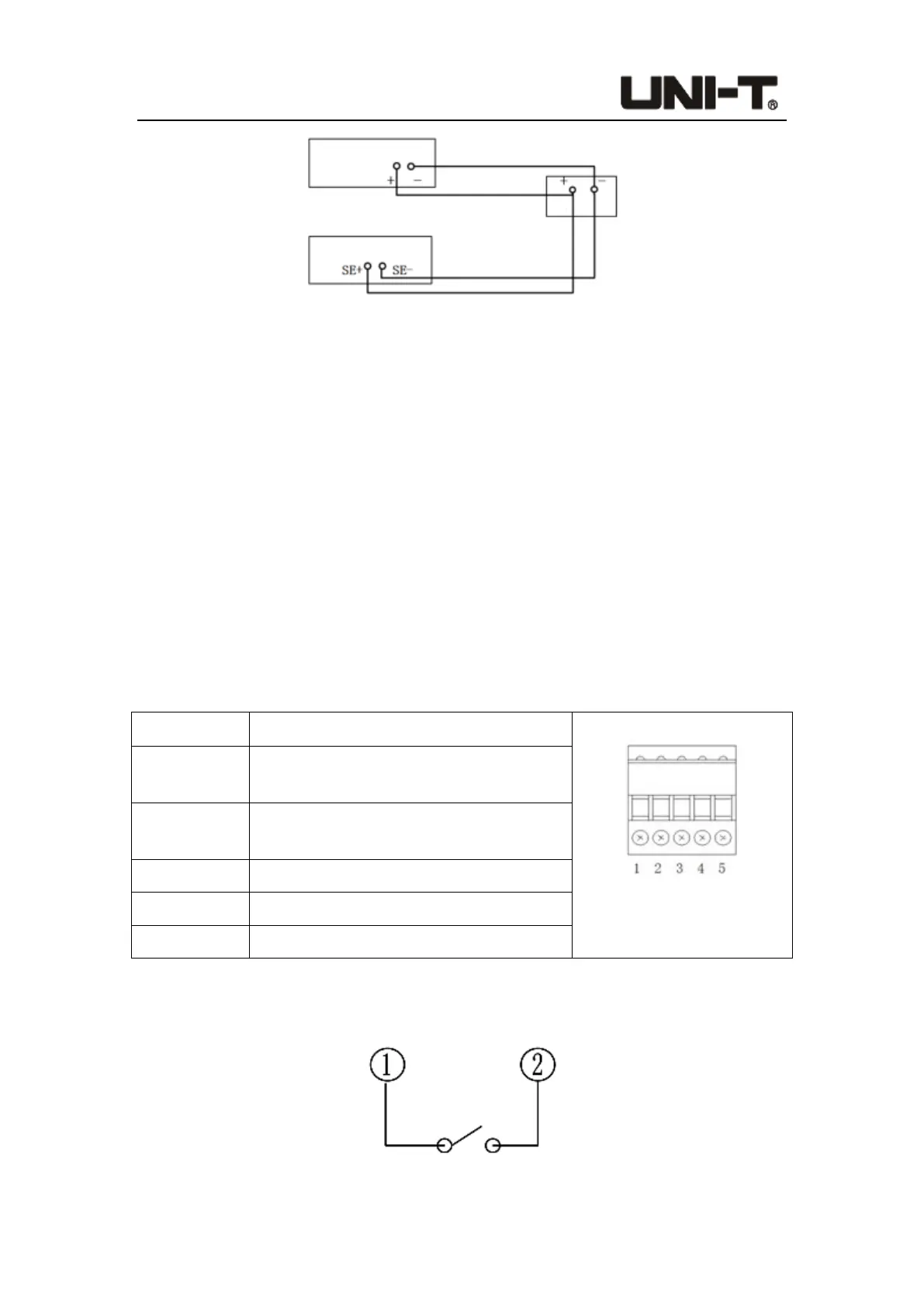
Figure 7-3 Wiring Diagram of Remote Compensation
SE+ and SE- are remote input terminals. In order to avoid the voltage drop caused by too
long load input leads, remote test allows to measure directly on the input terminal source
to improve measurement accuracy.
7.4 Trigger Signal Terminal
The external trigger signal is a voltage trigger. When a voltage signal of DC5V~DC24V is
given, the trigger is valid; when there is no voltage, the trigger is invalid. The current
monitoring output is a voltage output, and the output signal range is 0~10V. The real-time
current from zero to full range is indicated. The output signal impedance is less than or
equal to 10kΩ.
Description of terminals:
Terminal NO. Description
Trigger signal terminal
diagram
1
Passive trigger positive / test result power
supply positive
2
Passive trigger negative/active trigger
positive
3 Ground (GND)/active trigger negative
4 Test result output 1 (incorrect detection)
5 Test result output 2 (correct detection)
Wiring instructions:
1. Wiring method for passive trigger input (external passive switch)
Front panel-input terminal
Rear panel-measurement terminal
Object under test
 Loading...