EasyManuals Logo
Home>Universal Robots>Robotics>UR e Series

Universal Robots UR e Series Installation Guide

Universal Robots UR e Series
40 pages
To Next Page IconTo Next Page
To Previous Page IconTo Previous Page
Page #19 background imageLoading...
Page #19 background image
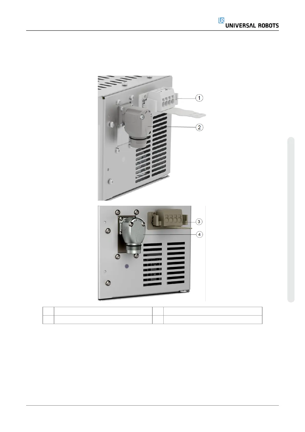
5.4. Robot Connection
The robot arm connector, illustrated below, is next to the power supply connector. For details on
connecting the robot arm cable, refer to the Universal Robots User Manual.
1 Robot arm connector 2 OEM CB connector
3 Robot arm connector (e-Series) 4 OEMCBconnector (e-Series)
5.5. Circuit Breaker Installation
Use a double pole circuit breaker to protect the power input connector, as it can also be used as a
switch. If a fuse is used, then a two-pole switch must be installed between the fuse and power input
connector.
Installation Guide OEM Control Box
Copyright © 2019–2024 by UniversalRobotsA/S. All rights reserved.

Other manuals for Universal Robots UR e Series

Questions and Answers:

Question and Answer IconNeed help?

Do you have a question about the Universal Robots UR e Series and is the answer not in the manual?

Universal Robots UR e Series Specifications

General IconGeneral
BrandUniversal Robots
ModelUR e Series
CategoryRobotics
LanguageEnglish

Related product manuals