16
DS1083-048
ADVANCED CONFIGURATION
To go to advanced conguration, put both the rotary switches on position 9.
The door unit emits an acoustic signal and turns the signalling yellow led on.
At the end of operations, put again the door unit in stand-by mode, changing the position of one of the
rotary switches at least.
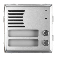
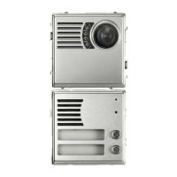
CONTROL CAMERAS (Only for 1083/78 and 1083/79)
If in a call module are present the control cameras, the function must be programmed.
1. Go to the advanced conguration, by setting both the rotary switches to position 9; the door unit emits
a beep to indicate the programming state and turns the yellow led on.
2. Press the hall button (PA – CT) for the same times number as the present control cameras number. Each
time the button is pressed, the door unit emits the same beep number as the programmed cameras
number (5 max); by pressing again the button after 5 beeps, a long beep is emitted, to indicate that 0
cameras are connected (default).
3. Put again the rotary switches on the correct position to exit from the advanced conguration. The yellow
led turns off.
BUTTON CODES
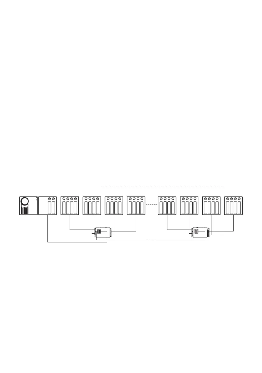
Up to 62 buttons (in addition to the basic buttons) may be connected to the door unit using up to 4 button
expansion modules 1083/17.
By default the buttons are associate to the users from 0 to 63 of the column to which it belongs if the door
unit is congured as secondary unit.
If instead the door unit is congured as main unit, then the buttons are automatically associated to the
column 0, which simplies the installation of main units in single column systems.
USER= 2
USER= 3
USER= 0
USER= 1
USER= 4
USER= 5
USER= 6
USER= 7
USER= 8
USER= 9
USER= 62
USER= 63
P1÷P4
P5÷P8
P13÷P16
P9÷P12
OUTPUT
INPUT
OUTPUT
P13÷P16
P9÷P12
P5÷P8
P1÷P4
1083/17 (1) 1083/17 (4)
Instead, if the door unit is congured as main unit and several columns are present in the system, an
association must be created between the buttons and the users of the different column proceed as
follows:
Access advanced conguration by turning the two rotary switches to position 99 (the yellow LED will
light up).
Set the ID dip-switch to the code of the rst column in the system (column 0 typically).
Press the button corresponding to user 0 of the selected column. All the subsequent buttons will be
automatically associated to the users of the column itself in sequence.
Repeat the operation on all the columns.
Reset the ID dip-switch in start position.
To quit advanced conguration, turn the two rotary switches to the door opening line and the guaranteed
conversation time setting positions. The yellow LED will go out.
Example:
System with 3 columns, the rst with 4 users, the second with 6 users and the third with 8 users.
Access advanced conguration.
Set the ID dip-switch to 0.
Press the upper button of the door unit (rst button).
Set the ID dip-switch to 1.
•
•
•
•
•
•
•
•
•
•
•
 Loading...