36 HC 35 E • HC 45 E • HC 55 E
g
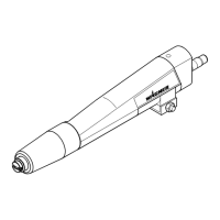
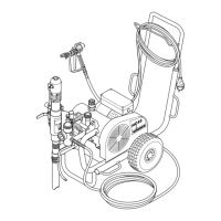
1 Spray gun
2 High-pressure hose
3 Electric motor
4 ON/OFF switch
5 Control lamp shows that the unit is ready
for operation HC 35 E, HC 45 E, HC 45 E-SSP
6 Unit connection line (230 V)
7 Extractable shaft
8 Control lamp shows that the unit is ready
for operation HC 55 E, HC 55 E-SSP
9 ON/OFF switch (400 V)
HC 55 E, HC 55 E-SSP
10 V-belt under the belt cover
11 Return hose
12 Suction tube
13 High-pressure filter
14 Material feed pump
HC 45 E, HC 55 E
15 Material feed pump
HC 45 E-SSP, HC 55 E-SSP
Description of unit
3.3 Explanatory diagram legend HC units
16 Material feed pump HC 35 E
17 Manometer
18 Retention pin for the swivel mechanism
19 Filling orifice for separating oil
(separating oil prevents increased wear
and tear of the packings)
20 Ball valve lever position horizontal –
hydraulic motor switched off
lever position vertical –
hydraulic motor switched on
21 Handle for swiveling the material feed pump
22 Hydraulic motor
23 Relief valve knob
Turn left for circulation k
Turn right for spray p
24 Hydraulic oil pump
25 Pressure regulating knob
26 Oil measuring stick
 Loading...