Benchmark Platinum-Edge: Operation-Service Manual
SECTION 9 – AERTRIM OPERATION
OMM-0137_D • GF-211 • 7/16/2019 Technical Support • (800) 526-0288 • Mon-Fri, 8 am - 5 pm EST Page 120 of 146
AERtrim Activation Instructions
1. Record the following information from the unit you wish to activate. To do this, go to the
Main Menu Advanced Setup Performance AERtrim AERtrim Settings and
scroll down until you see the following parameters:
• Unit Serial #, found on the unit’s code plate. For example, G-18-1050
• Trim ID
• Fixed ID
2. Contact AERCO Sales Administration with the information found in step 1. They will
provide you with an activation code.
3. Once you have obtained the activation code, go back to Main Menu Advanced Setup
Performance AERtrim AERtrim Settings.
4. Find the Activation Code parameter, enter the activation code and press Save.
5. Scroll back to the top of the AERtrim Settings screen and set the AERtrim parameter to
Enabled.
6. Go to the AERtrim O2 Trim Parameters screen. The O2 Target, O2
Upper Limit and
O2 Lower Limit parameters are at default values but can be changed as needed.
NOTE: For full instructions, including all menu options, see the Edge Controller Manual,
Section 6.6.1: AERtrim.
9.3 OPERATION DETAILS
During operation, the AERtrim system will adjust the command voltage sent to the combustion
air blower within a limited range. The amount of voltage trim depends on the error between the
desired O
2
% (target %) and the current reading of the O
2
sensor (O
2
%) and also on high and
low limits of blower voltage for each valve position. The total amount of corrective voltage trim
is limited by the controller to insure safe and reliable operation of the system.
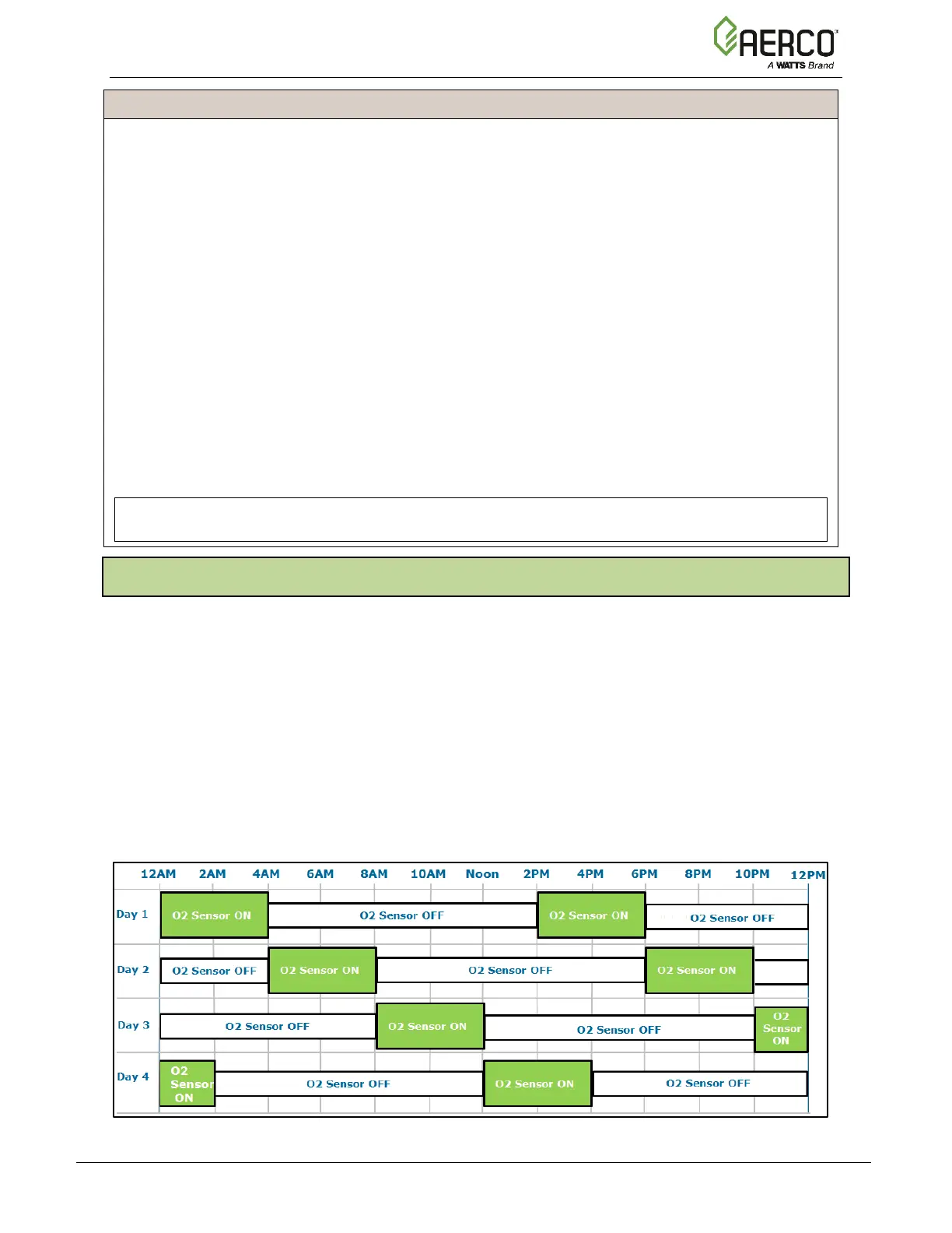
The AERtrim system has a rolling active/inactive operation based on 4 hours on / 10 hours off
sequence. Since this is a trim function and not an active control function, the trim activity can
make adjustments in the blower voltage calibration values on the 4/10 schedule to effectively
control the air/fuel mixture without continuous operation of the sensor. This method achieves
the objective for long term efficiency of boiler operation while maximizing the sensor life in the
boiler environment. The 14 hour cycle insures that the 4 hour on period will be active for any
hour of the day every four days as shown below.
Figure 9-2: Active O
2
Sensor Cycle Coverage Chart
 Loading...