Benchmark Platinum-Edge: Operation-Service Manual
SECTION 7 – BOILER SEQUENCING TECHNOLOGY
OMM-0137_D • GF-211 • 7/16/2019 Technical Support • (800) 526-0288 • Mon-Fri, 8 am - 5 pm EST Page 83 of 146
7.3 BST Implementation Instruction
The instructions in the rest of this chapter refer to I/O board connections on the Benchmark
boilers. For an I/O board diagram and terminal connections, see Section 2.11.1 in Benchmark
Platinum-Edge: INSTALLATION Manual (OMM-0136, GF-210).
7.3.1 Option 1 Constant Setpoint: Direct Wired Header Sensor
OPTION 1
Instructions: Constant Setpoint with Direct Wired Header Sensor
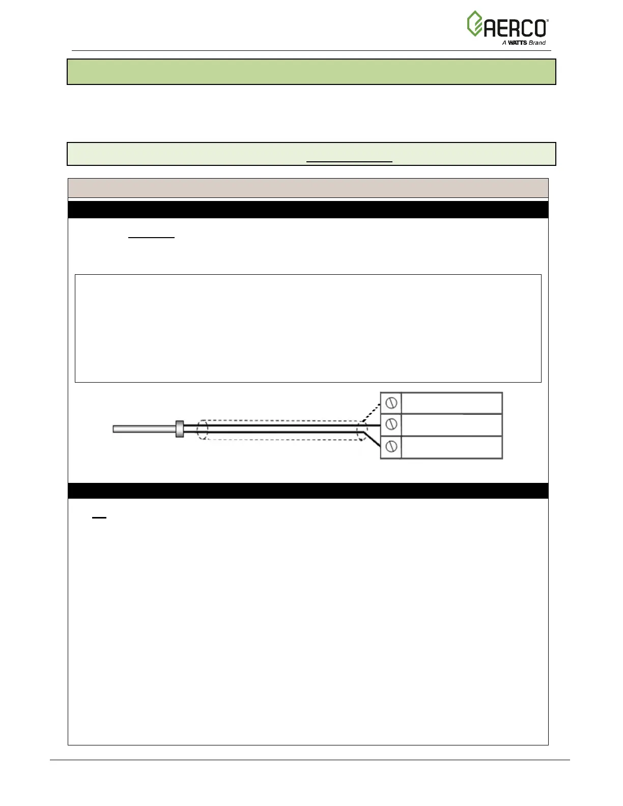
Step 1: HEADER SENSOR WIRING – MANAGER Unit
1. On the Manager unit, connect the Header Temperature Sensor (P/N 24410) to the I/O
board terminal strip J3, terminals 4 (Supply Header +) and 5 (Supply Header –).
2. Ground the shield to any Shield terminal on the I/O Board, such as Terminal 3 or 8.
NOTES:
• The Header Sensor must be installed between 2 and 10 feet (0.61 and 3.1m)
downstream of the LAST boiler in the plant’s supply water header.
• Shielded pair 18 - 22 AWG cable is recommended for header sensor wiring. There is no
polarity to be observed.
• The ground for the shield is at the Shield terminal on the I/O the board. The sensor end
of the shield must be left free and ungrounded.
Step 2: OPTION 1 CONFIGURATION
On All Boiler:
1. Go to: Main Menu Advanced Setup BST Cascade Cascade Configuration:
• Set the Unit Mode parameter to BST Client.
2. Go to: Main Menu
Advanced Setup BST Cascade Application Configuration:
• Set the Unit Address parameter to the communication address of the unit.
Continued on next page
HEADER TEMP SENSOR (P/N 24410)
 Loading...