Benchmark Platinum-Edge: Operation-Service Manual
SECTION 7 – BOILER SEQUENCING TECHNOLOGY
OMM-0137_D • GF-211 • 7/16/2019 Technical Support • (800) 526-0288 • Mon-Fri, 8 am - 5 pm EST Page 89 of 146
7.3.4 Option 4 Outdoor Reset: Modbus Header Sensor & Modbus
Outdoor Sensor
OPTION 4
Instructions: Outdoor Reset, Modbus Header Sensor & Modbus Outdoor Sensor
NOTE:
Both Header Sensor AND Outdoor Sensor must be wired. See the Edge Controller Manual
and (OMM-0139, GF-213) for more information.
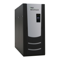
Step 1: HEADER SENSOR WIRING – ANY BOILER
1. Connect the Modbus Transmitter (P/N 65169) terminal Pin B to the I/O Board strip J3,
terminal 13 (BST RS485+) and Pin A to terminal 15 (BST RS485–) on any of the Boiler
units using Shielded pair 18 - 22 AWG cable.
2. Using Shielded pair 18 - 22 AWG cable, connect the Header Temperature Sensor (P/N
24410) to pins 2 and 3 of the Modbus Transmitter.
3. Install a jumper wire between pins 1 and 2 of the Modbus Transmitter.
NOTES:
• Polarity must be observed for the RS485 connections.
• Ground the shield to any Shield terminal on the I/O Board, such as Terminal 3 or 8.
• The Header Sensor must be installed between 2 and 10 feet (0.61 and 3.1m)
downstream of the LAST boiler in the plant’s supply water header.
• There is no polarity to be observed. The ground for the shield is at the power supply
ground. The sensor end of the shield must be left free and ungrounded.
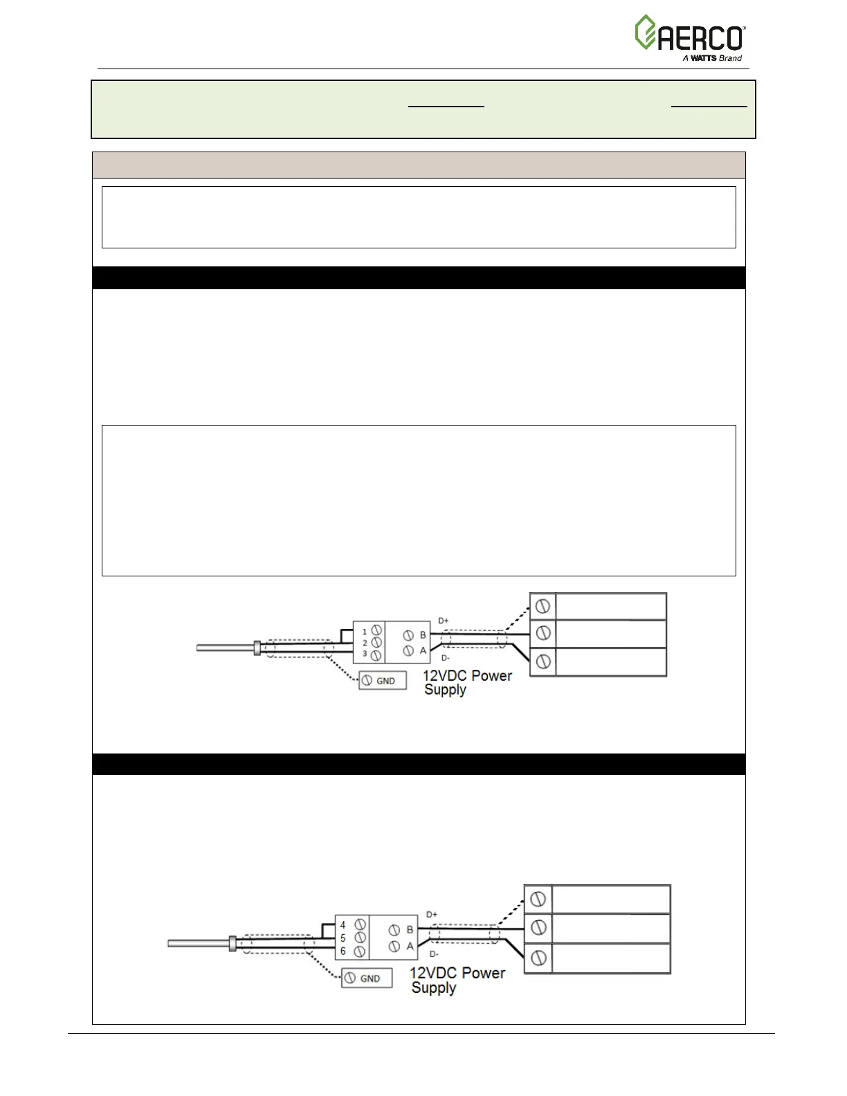
Step 2: OUTDOOR SENSOR WIRING
1. If you have not already done so, complete step 1 of the instructions above to connect the
Modbus Transmitter to the I/O Board.
2. Connect the Outdoor Temperature Sensor (P/N 61048) to Pins 5 and 6 of the Modbus
Transmitter using a Shielded pair 18 - 22 AWG cable.
3. Install a jumper wire between Pins 4 and 5 on the Modbus Transmitter.
HEADER TEMP SENSOR
(P/N 24410)
(P/N 61048)
 Loading...