Phaser 4500/4510 Service Manual 10-3
Wiring Diagrams
Print Engine Plug/Jack Locator
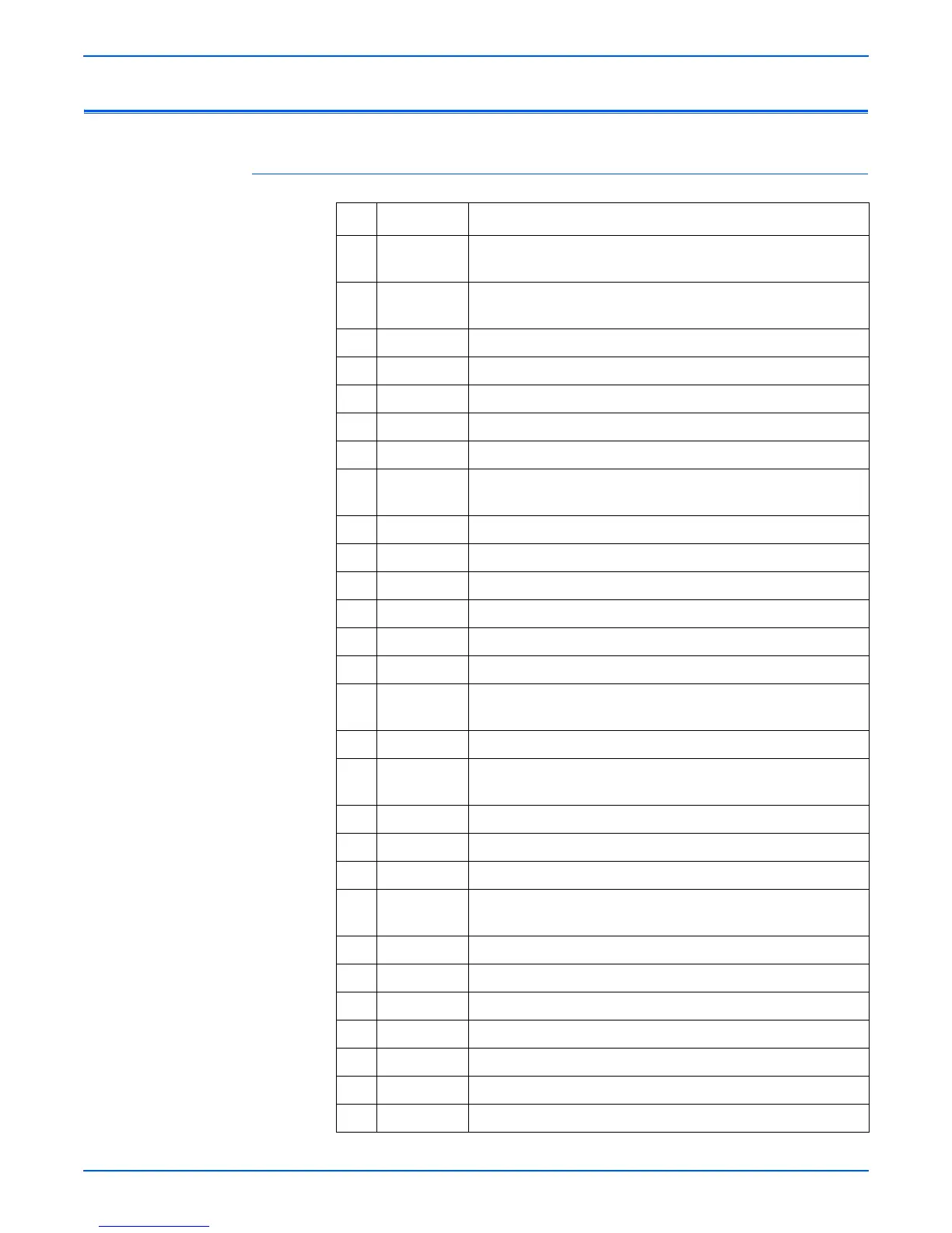
P/J Locator Table
P/J Coordinates Remarks
10 G-108 Connects the LVPS harness assembly and HVPS/engine logic
board
11 G-108 Connects the LVPS harness assembly and HVPS/engine logic
board
13 G-109 Connects the laser unit harness and HVPS/engine logic board
14 G-109 Connects the laser unit harness and HVPS/engine logic board
15 G-109 Connects the ANT harness and HVPS/engine logic board
16 G-110 Connects the laser unit harness and HVPS/engine logic board
17 G-110 Connects the laser unit harness and HVPS/engine logic board
18 G-110 Connects the LVPS harness assembly and HVPS/engine logic
board
19 G-109 No connection
20 G-110 Connects the feeder harness 1 and HVPS/engine logic board
22 H-109 Connects the toner harness and HVPS/engine logic board
24 H-109 Connects the chute harness and HVPS/engine logic board
25 — Non-existent
26 H-109 Connects the low paper sensor and HVPS/engine logic board
27 G-109 Connects the LVPS harness assembly and HVPS/engine logic
board
28 H-109 Connects the HVPS/engine logic board to I/P Board
29 H-107 Connects the exit sensor harness 1 and HVPS/engine logic
board
30 H-107 Connects the stacker harness and HVPS/engine logic board
31 G-108 Connects the print cartridge Guide and HVPS/engine logic board
32 H-109 No connection
40 U-122
V-122
P4500: 3.3 VDC Output from the LVPS to the DC-DC converter
P4510: 3.3 and 5 VDC output from the LVPS to the I/P board
41 U-122 Connects the LVPS harness assembly and LVPS
42 U-122 Connects the LVPS harness assembly and LVPS
43 U-122 Connects the main motor and LVPS
44 U-122 Connects the rear cover switch and LVPS
45 U-123 Connects the 24 V Interlock and LVPS
46 U-123 Connects the fuser harness assembly and LVPS
47 T-124 Connects the fuser harness assembly and LVPS
 Loading...


