ML505/ML506/ML507 Evaluation Platform www.xilinx.com 47
UG347 (v3.1.1) October 7, 2009
Detailed Description
R
The native output of the ICS843001-21 is LVPECL, so a resistor network is present to
change the voltage swing to LVDS levels. The LVDS output is then multiplexed out
through Series AC coupling capacitors to allow the clock input of the FPGA to set the
common mode voltage.
SATA GTP/GTX Transceiver Clock Generation
An Integrated Circuit Systems ICS844051-1 chip generates a high-quality, low-jitter,
75-MHz or 150-MHz LVDS clock from an inexpensive 25-MHz crystal oscillator. This clock
is sent to the GTP/GTX transceiver driving the SATA connectors. Jumper J56 sets the
SATA GTP/GTX transceiver clock frequency (see Table 1-32). Series AC coupling
capacitors are also present to allow the clock input of the FPGA to set the common mode
voltage.
SGMII / Loopback GTP/GTX Transceiver Clock Generation
An Integrated Circuit Systems ICS844021I chip generates a high-quality, low-jitter,
125-MHz LVDS clock from an inexpensive 25-MHz crystal oscillator. This clock is sent to
the GTPs driving the SGMII or onboard loopback interfaces. Series AC coupling capacitors
are also present to allow the clock input of the FPGA to set the common mode voltage.
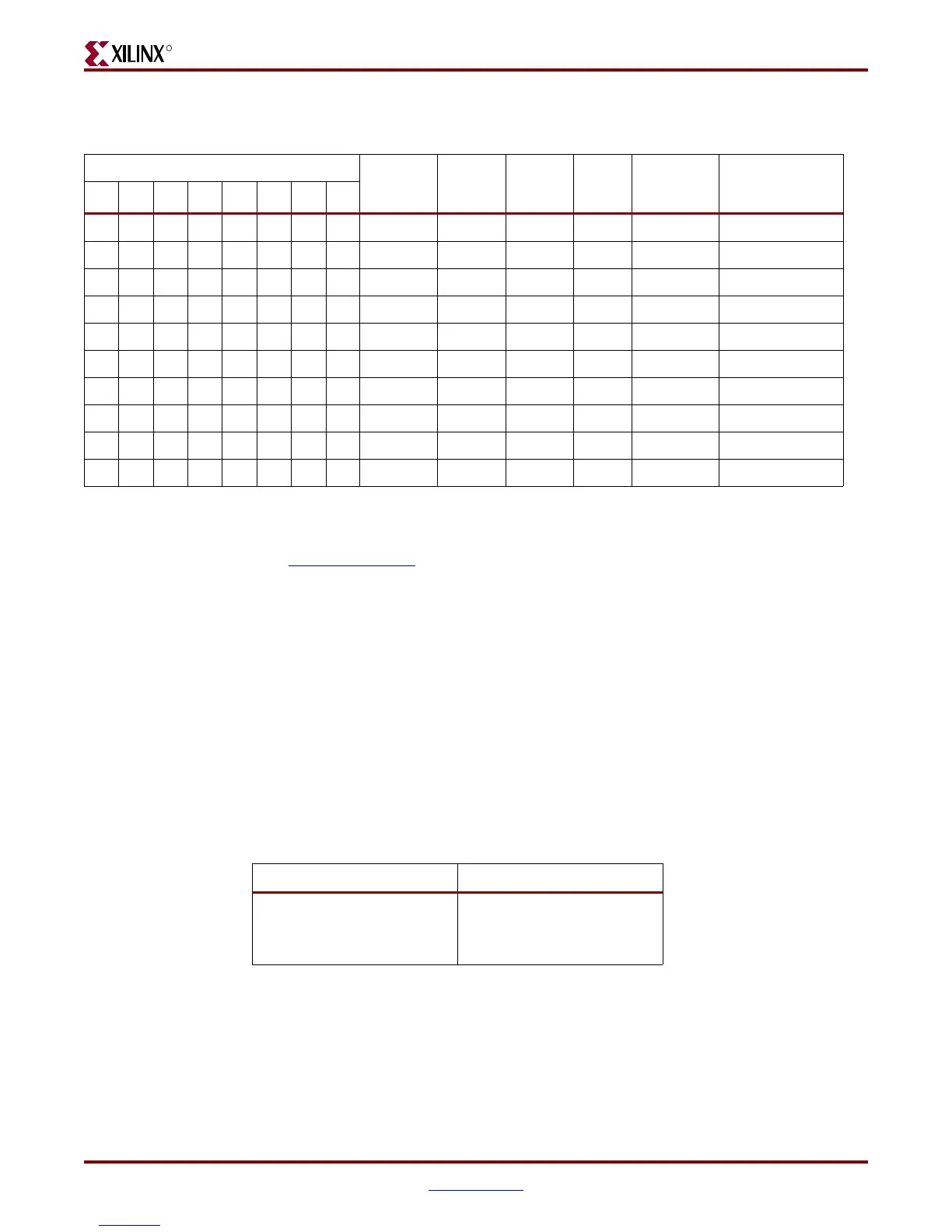
Table 1-31: Configurations for Clock Source and Frequency Options
DIP Switch SW6 [1:8] Value Input Ref
Clock
(MHz)
M Divider
Value
N Divider
Value
V
CO
(MHz)
Output
Frequency
(MHz)
Application
N0 N1 N2 M0 M1 M2 SEL1 SEL0
11000101 19.44 32 4 622.08 155.52 SONET
01100101 19.44 32 8 622.08 77.76 SONET
00000101 19.44 32 1 622.08 622.08 SONET
10000101 19.44 32 2 622.08 311.04 SONET
00111010 25 25 5 625 125 Gigabit Ethernet
11111010 25 25 10 625 62.5 Gigabit Ethernet
10101010 25 24 6 600 100 PCI Express
11001010 25 24 4 600 150
(1)
SATA
01101010 25 24 8 600 75 SATA
11011010 25 25 4 625 156.25 XAUI/SRIO
Notes:
1. Factory default setting.
2. A 1 equates to the DIP switch in the on position.
3. For Fibre Channel support, see Answer Record 24918
.
Table 1-32: Configuration for SATA GTP/GTX Clock Signals
SATA Clock Signal Board Connection
SATA Clock Frequency
Jumper J56
• Jumper Off = 75 MHz
• Jumper On = 150 MHz
Downloaded from Elcodis.com electronic components distributor

 Loading...


