50 www.xilinx.com ML605 Hardware User Guide
UG534 (v1.9) February 26, 2019
Chapter 1: ML605 Evaluation Board
FPGA INIT and DONE LEDs
The typical Xilinx FPGA power up and configuration status LEDs are present on the
ML605.
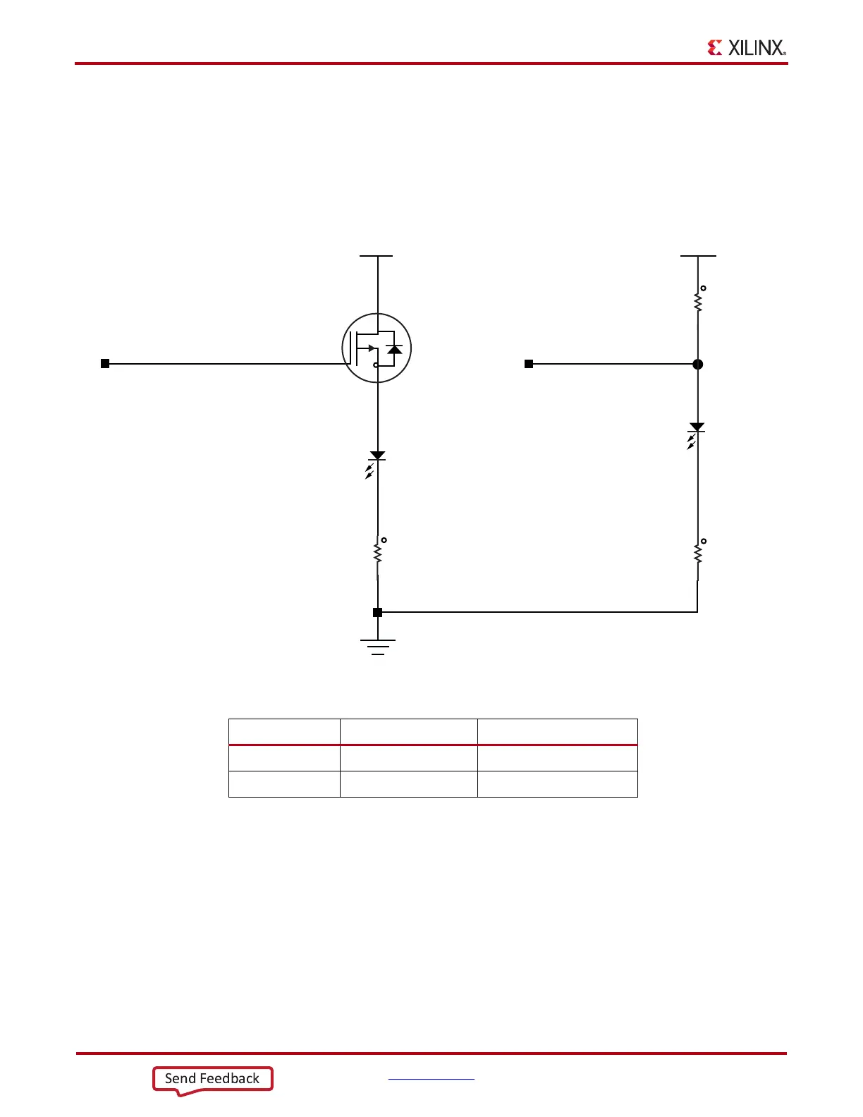
The red INIT LED DS31 comes on momentarily after the FPGA powers up and during its
internal power-on process. The DONE LED DS13 comes on after the FPGA programming
bitstream has been downloaded and the FPGA successfully configured.
17. User I/O
The ML605 provides the following user and general purpose I/O capabilities:
• User LEDs (8) with parallel wired GPIO male pin header
• User Pushbutton (5) switches with associated direction LEDs
• CPU Reset pushbutton switch
•User DIP switch (8-pole)
• User SMA GPIO
• LCD Display (16 char x 2 lines)
X-Ref Target - Figure 1-17
Figure 1-17: FPGA INIT and DONE LEDs
FPGA INIT B
NDS336P
FPGA_DONE
VCC2V5
VCC2V5
Q14
1
R419
330
5%
1/16W
R4
27.4
1%
1/16W
R3
27.4
1%
1/16W
1
2
1
2
1
2
DS31
DS13
3 2
12
12
LED-RED-SMT
LED-GRN-SMT
UG534_17_050510
Table 1-20: FPGA INIT and DONE LED Connections
FPGA U1 Pin Schematic Net Name Controlled LED
P8 FPGA_INIT_B DS31 INIT, Red
R8 FPGA_DONE DS13 DONE, Green

 Loading...


