4 Operate panel
4.1 Basic operation
4.1.1 Operating panel description
The panel will be self-checked, and all the display digital tubes and five decimal points will be lit for
one second at the same time.
4.1.2 Button operation
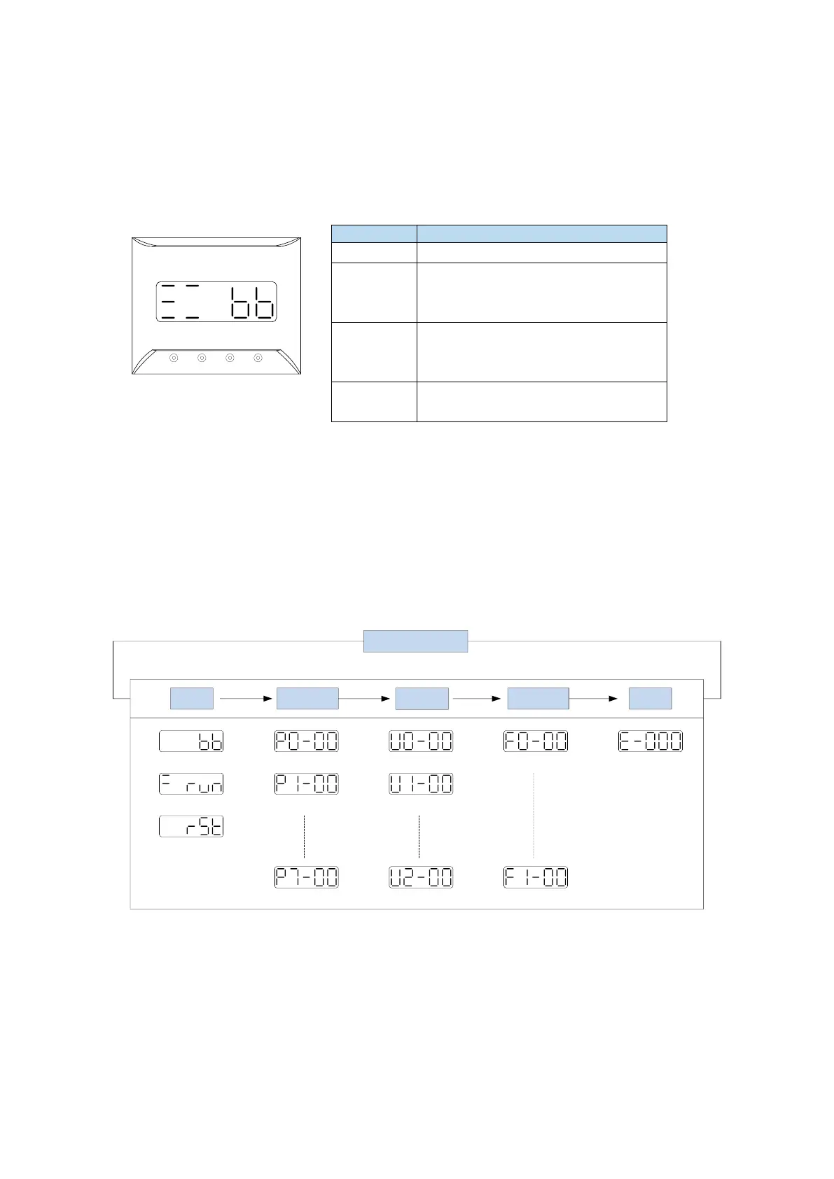
By switching the basic state of the panel operator, it can display the running state, set parameters, run
auxiliary functions and alarm state. After pressing the STA/ESC key, the states are switched in the
order shown in the following figure.
State: BB indicates that the servo system is idle; run indicates that the servo system is running; RST
indicates that the servo system needs to be re-energized.
idle
run
reset
Function parameter
Control parameter
Communication
parameter
Power on times
Jog
Alarm code
Alarm code
Present speed Alarm clear
state Parameter
Monitor
Auxiliary Alarm
STA/ESC switch
Parametric setting Px-xx: The first X represents the group number, and the last two X
represents the parameter serial number under the group.
Monitor status Ux-xx: The first X represents the group number, and the last two X represents
the parameter number under the group.
Auxiliary function Fx-xx: The first X denotes the group number, and the last two X denotes
the parameter number under the group.
Alarm state E-xxx: The first two X denote the alarm category, and the last x denotes the
small category under the category.
Short press: state switch, state return
Short Press: The display data increases
Long press: The display data increases
continuously
Short Press: The display data decreases
Long press: The display data decreases
continuously
Long press: Set and view parameters.

 Loading...
