EasyManua.ls Logo

Xinje DS5L1 Series User Manual

Xinje DS5L1 Series
171 pages
To Next Page IconTo Next Page
To Previous Page IconTo Previous Page
Page #82 background imageLoading...
Page #82 background image
Because it can only rotate in one direction, after a certain period of time, the number of revolving
cycles will always exceed the upper limit of absolute value encoder.
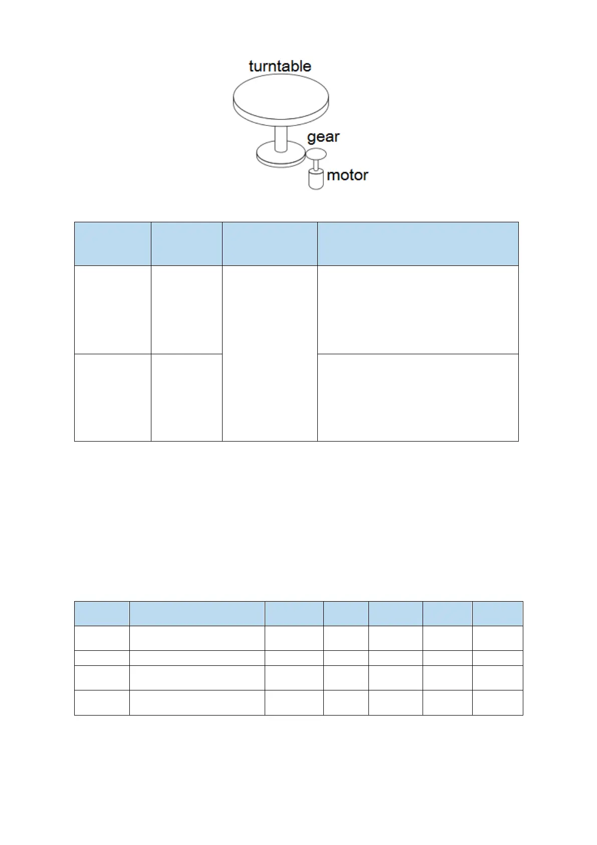
Servo motor
series
Resolution
(single-circle
data)
Rotating Circle
Serial Data
Output range
Operation of overtime
CM/T
17
-32768~32767
When it is higher than the upper limit value
in the forward direction (+32767*2^ 17):
Rotation serial data = 32767*2^17
When it is below the lower limit of reversal
direction (-32768*2^ 17):
Rotation Serial Data=-32767*2^17
TL
23
When it is higher than the upper limit value
in the forward direction (+32767*2^23):
Rotation serial data = 32767*2^23
When it is below the lower limit of reversal
direction (-32768*2^ 23):
Rotation Serial Data=-32767*2^23
5.7 Auxiliary functions
5.7.1 Anti-blocking protection
Anti-blocking alarm: When the motor speed is lower than P0-75 (unit 1 rpm) and the duration reaches
the set value of P0-74 (unit ms), the current output torque U0-02 is greater than the internal positive
torque limit of P3-38 and the internal reverse torque limit of P3-39, it will show the alarm E-165
blocking overtime.
Related parameters
Parameter
Meaning
Default
setting
Unit
Range
Modify
Effective
P0-74
Blocking alarm time
According
to models
1ms
065535
Anytime
At once
P0-75
Blocking alarm speed
50
rpm
59999
Anytime
At once
P3-38
Anti-blocking alarm internal
forward torque limit
300
%
0300
Anytime
At once
P3-39
Anti-blocking alarm internal
reverse torque limit
300
%
0300
Anytime
At once
Note:
(1) When P0-74 or P0-75 is set to 0, this alarm will not be detected;
(2) If this alarm occurs during normal operation of servo, please confirm:
(a) Monitor U0-02 motor torque and check if P3-38 and P3-39 torque limits are set properly;
(b) Check the external mechanical structure and installation;
(3) P0-74 the default value of locked rotor alarm time is as follows:

Table of Contents

Question and Answer IconNeed help?

Do you have a question about the Xinje DS5L1 Series and is the answer not in the manual?

Xinje DS5L1 Series Specifications

General IconGeneral
BrandXinje
ModelDS5L1 Series
CategoryServo Drives
LanguageEnglish

Summary

Contact Information

Declaration of Liability

Outlines the manufacturer's liability and disclaimer regarding manual content.

Contact Information

Lists contact details for Wuxi Xinje Electric Co., Ltd.

Safety Precautions

Attention to Product Confirmation

Details checks to ensure product integrity before installation and use.

Installation Notes

Provides crucial notes for safe and correct installation procedures.

Cautions for Wiring

Highlights essential precautions and guidelines for electrical wiring.

Operation Cautions

Maintenance and Inspection

Provides guidance on maintaining and inspecting the servo driver and motor.

Wiring Attention

Offers specific advice and warnings related to wiring practices.

Servo System Selection

Servo Driver Selection

Covers selecting the appropriate servo driver based on model name and specifications.

Servo Motor Selection

Guides the selection of servo motors based on model naming conventions.

Cable Selection

Outlines the process for selecting appropriate cables for the servo system.

Selection of Other Accessories

Covers the selection of additional accessories like regenerative resistance.

Installation of Servo System

Servo Driver Installation

Details the site, environment, and standards for servo driver installation.

Servo Motor Installation

Provides instructions for installing servo motors, including cautions.

Servo Cable Installation

Covers cable selection and installation for servo systems.

Servo Driver Dimensions

Servo Driver Dimensions

Provides dimensional drawings for different DS5L1 servo driver models.

Servo Motor Dimensions

Shows installation dimensions for various servo motor series.

Servo System Wiring

Main Circuit Wiring

Details the main circuit wiring, including terminal arrangements and explanations.

Signal Terminals: Classification and Function

Categorizes and explains the functions of various signal terminals.

Operate Panel

Basic Operation

Covers the basic operation of the control panel, including button functions and state switching.

Operation Display

Describes the display contents for speed torque and position control modes.

Group U Monitor Parameters

Details the U0-21 input signal status and distribution.

Group F Auxiliary Function Parameters

Group F0 Auxiliary Functions

Lists function codes and descriptions for Group F0 auxiliary functions.

Group F1 Auxiliary Functions

Lists function codes and descriptions for Group F1 auxiliary functions.

Fault Alarm Handling

Current Sampling Zero-Correction (F1-02)

Explains the use of current sampling zero-correction.

Forced Enable (F1-05)

Describes how to force enable the servo using F1-05.

Reset Turns of Absolute Encoder (F1-06)

Refers to resetting the absolute encoder turns.

Parameter Setting Example

Parameter Setting Example

Provides an example of changing a parameter value.

Change Motor Code

Guides on matching the motor code for servo system setup.

Operation of Servo System

Control Mode Selection and Switching

Explains how to select and switch between different control modes.

Basic Function Setting

Covers inching and trial operations for ensuring normal servo system function.

Servo Enable Setting

Explains how to set servo enable signals for motor operation.

Rotation Direction Switching

Rotation Direction Switching

Describes how to change the motor's rotation direction using parameters.

Stop Mode

Details inertia and deceleration shutdown modes for servo control.

Power-Off Brake

Power-Off Brake Function

Explains the function and use of the power-off brake for vertical loads.

Braking Setting

Covers braking settings, including regenerative power and resistance specifications.

Position Control

General Position Control

Explains general position control, including electronic gear ratio.

Positioning Completion Signal

Explains signals indicating servo motor positioning completion.

Positioning Near Signal

Describes the /NEAR signal for positioning approach detection.

Command Pulse Prohibition

Explains how to prohibit command pulse input using /INHIBIT.

Offset Clear

Details the /CLR signal for clearing position offset.

Position Command Filter

Explains filters for position command acceleration/deceleration and smoothing.

Reference Origin

Describes how to find the reference origin for positioning control.

Position Control (External Pulse Command)

External Pulse Position Mode

Details the external pulse position mode settings.

Pulse Instruction Direction and Form

Explains how to set pulse instruction direction and form.

Position Control (Internal Command)

Internal Position Mode

Explains the internal position mode settings.

Internal Position Mode Setting

Covers settings for waiting mode and change step mode.

Position Segment Settings

Position Segment 1 to 35 Parameter Settings

Details parameters for setting up to 35 position segments.

Change Step Signal (/CHGSTP)

Explains the /CHGSTP signal for changing position segments.

Skip Present Segment Signal (/ZCLAMP)

Describes the /ZCLAMP signal for skipping current segments.

Speed Control

Speed Mode General Control

Covers general controls for speed mode, including soft start and zero clamp.

Speed Reach Signal (/V-RDY)

Describes the /V-RDY signal for indicating speed attainment.

Speed Command Filter

Explains filters for speed command signals.

Speed Control (Internal Speed)

Covers speed control using internal settings.

Speed Control (Pulse Frequency Command)

Torque Control

Torque General Mode

Covers general torque control modes.

Torque Control (Internal Setting)

Covers torque control using internal settings.

Absolute Value System

Absolute System Setting

Explains the setup for absolute value encoders and battery installation.

Replace the Battery

Provides instructions for replacing the encoder battery.

Auxiliary Functions

Anti-blocking Protection

Explains anti-blocking protection and related parameters.

Torque Limit

Details internal and external torque limits and their relationships.

Speed Limit

Covers forward and reverse maximum speed limits.

I/O Signal Distribution

Explains the distribution of input and output terminals.

Output Terminal Function

Explains the functions of various output terminals.

Input Terminal Function

Explains the distribution and functions of input terminals.

Time Limit Curve of Overload Protection

Servo Gain Adjustment

Overview of Servo Gain Adjustment

Introduces servo gain adjustment and the overall process.

Model Loop Control

Explains the function and impact of the model loop control.

Torque Disturbance Observation

Explains how to observe and compensate for torque disturbances.

Rotary Inertia Presumption

Overview

Introduces the function of estimating load inertia.

Notes on Inertia Presumption

Provides notes on occasions where inertia presumption may fail or is not applicable.

Operation Steps for Inertia Estimation

Details the steps for estimating inertia using the driver panel.

Rigidity Level Corresponding Gain Parameters

Auto-tuning

Overview of Auto-tuning

Introduces auto-tuning, covering internal and external instruction methods.

Internal Instruction Auto-tuning Steps

Details steps for internal auto-tuning using the driver panel.

External Instruction Auto-tuning Steps

Provides detailed steps for external auto-tuning.

Manual Adjustment

Overview of Manual Adjustment

Provides an overview of manual adjustment for servo gain.

Adjustment Steps

Details steps for increasing response and reducing vibration/overshoot.

Gain Parameters for Adjustment

Lists key gain parameters requiring adjustment.

Adaptive Function

Overview of Adaptive Function

Introduces the adaptive function for stable response.

Notes on Adaptive Function

Provides important notes regarding adaptive function operation.

Operation Steps for Adaptive Function

Outlines the steps for operating the adaptive function.

Inertia Mode and Related Parameters

Inertia Mode and Related Parameters

Discusses inertia modes and related parameters for adaptive function.

Recommended Inertia Ratio Parameters

Offers recommended inertia ratio parameters for different load conditions.

Vibration Suppression

Overview of Vibration Suppression

Explains how vibration suppression works to eliminate mechanical resonance.

Operation Tools for Vibration Suppression

Lists tools and modes for vibration suppression.

Vibration Suppression (Panel)

Details panel vibration suppression modes and operation.

Vibration Suppression (PC Software)

Guides vibration suppression using PC software.

Vibration Suppression (Manual Setting)

Explains manual vibration frequency setting.

Vibration Suppression (Quick FFT)

Describes using quick FFT for vibration suppression.

Notch Filter

Gain Adjustment

Load Shaking

Discusses causes and countermeasures for load shaking.

Vibration

Explains causes and countermeasures for machine vibration.

Noise

Addresses causes and countermeasures for servo noise.

Alarm

Alarm Code List

Provides a comprehensive list of alarm codes, explanations, and properties.

Analysis of Alarm Types

Analyzes alarm types, their reasons, and solutions.

Appendix 1: Group P Parameters

Appendix 3: FX-XX Auxiliary Function Parameters

Appendix 4: Modbus Address List

Appendix 5: Q&A

Panel States (BB and Run)

Explains the meaning of BB and Run states on the panel.

Parameter Checking and Setting

Refers to chapter 4.6 for parameter checking and setting.

Changing Parameters in Enabled Status

Details changing parameters when the servo is enabled.

Restoring Factory Settings

Explains how to restore factory settings.

Bus Mode Support

Lists models supporting XNET and EtherCAT communication.

Brake Motor Wiring and Power Failure Adjustments

Covers brake motor wiring and parameter adjustments for power failure.

Changing Initial Motor Direction

Explains how to change the initial motor direction.

Switching Between Main and Sub-Modes

Describes switching between main and sub-modes.

PLC and Servo Connection Modes

Explains PLC to servo connection modes for NPN and PNP outputs.

Regenerative Resistance Connection and Parameters

Details external connection and parameter settings for regenerative resistance.

Tank Chain Service Life

Inquires about the service life of tank chains.

General Debugging Steps

Motor Empty Shaft Preliminary Debugging

Guides preliminary debugging steps for an empty shaft motor.

Debug Motor with Machine

Covers debugging the motor with the actual machine setup.

Application Example

Mode 6: Pulse Instruction Position Mode

Specifies the application example's mode.

Equipment Introduction

Describes the equipment used in the application example.

Analysis of Application Example

Analyzes the process and requirements of the application example.

Signal and Terminal Information

Lists signals and terminals relevant to the example.

Calculate Electronic Gear Ratio

Guides the calculation of the electronic gear ratio for the example.

Servo General Mode Parameters

Appendix 8.1 Basic Parameters

Lists basic servo parameters and their overview.

Appendix 8.2 External Pulse Position Mode Parameters

Lists general parameters for external pulse position mode.

Appendix 8.3 Internal Position Mode Parameters

Lists general parameters for internal position mode.

Appendix 8.4 Internal Torque Control Parameters

Lists general parameters for internal torque control.

Appendix 8.5 Internal Speed Control Parameters

Lists general parameters for internal speed control.

Appendix 8.6 External Pulse Speed Control Parameters

Lists general parameters for external pulse speed control.

Torque-Speed Characteristic Curve

Related product manuals