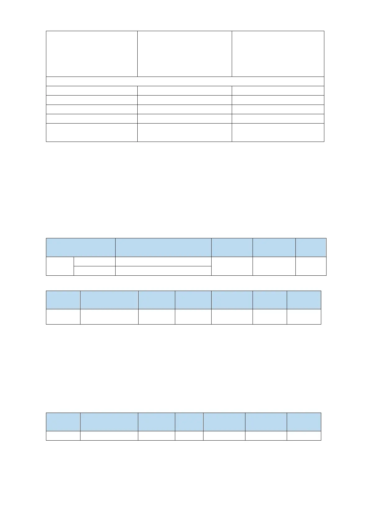
Load inertia ratio P0-07: 500%
speed loop gain P1-00: 200
speed loop gain P1-00: 800
speed loop gain P1-00: 800
speed loop integral P1-01: 3300
speed loop integral P1-01: 825
speed loop integral P1-01: 825
position loop gain P1-02: 200
position loop gain P1-02: 700
position loop gain P1-02: 700
Model loop gain P2-49: 300
Model loop gain P2-49: 300
Model loop gain P2-49: 4000
Phenomenon: Running jitter,
slow response
Phenomenon: smooth operation
and slow response
Phenomenon: smooth operation
and fast response
Note: The above curves only show the effect of the parameters, not the real running curves.
6.1.4 Torque disturbance observation
Disturbance observer can reduce the influence of external disturbance on servo system and improve the
anti-disturbance ability by detecting and estimating the external disturbance torque of the system and
compensating the torque command.
If the soft mode is selected in the auto-tuning mode, the disturbance observer will be closed
automatically, and the gain of the disturbance observer will not change. If the fast positioning or fast
positioning (control overshoot) is selected, the disturbance observer will be opened automatically, and
the gain of the disturbance observer will be modified to 85. The relevant parameters of this function no
need to be set manually by users.
Turn-off of disturbance observer
Turn-on of disturbance observer
Disturbance
observer gain
6.2 Rotary inertia presumption
6.2.1 Overview
Rotational inertia estimation is the function of automatic operation (forward and reverse) in the driver
and estimate the load inertia in operation.
Rotational inertia ratio (the ratio of load inertia to motor rotor inertia) is a benchmark parameter for
gain adjustment, and it must be set to the correct value as far as possible.

 Loading...
