VB5N series inverter
15
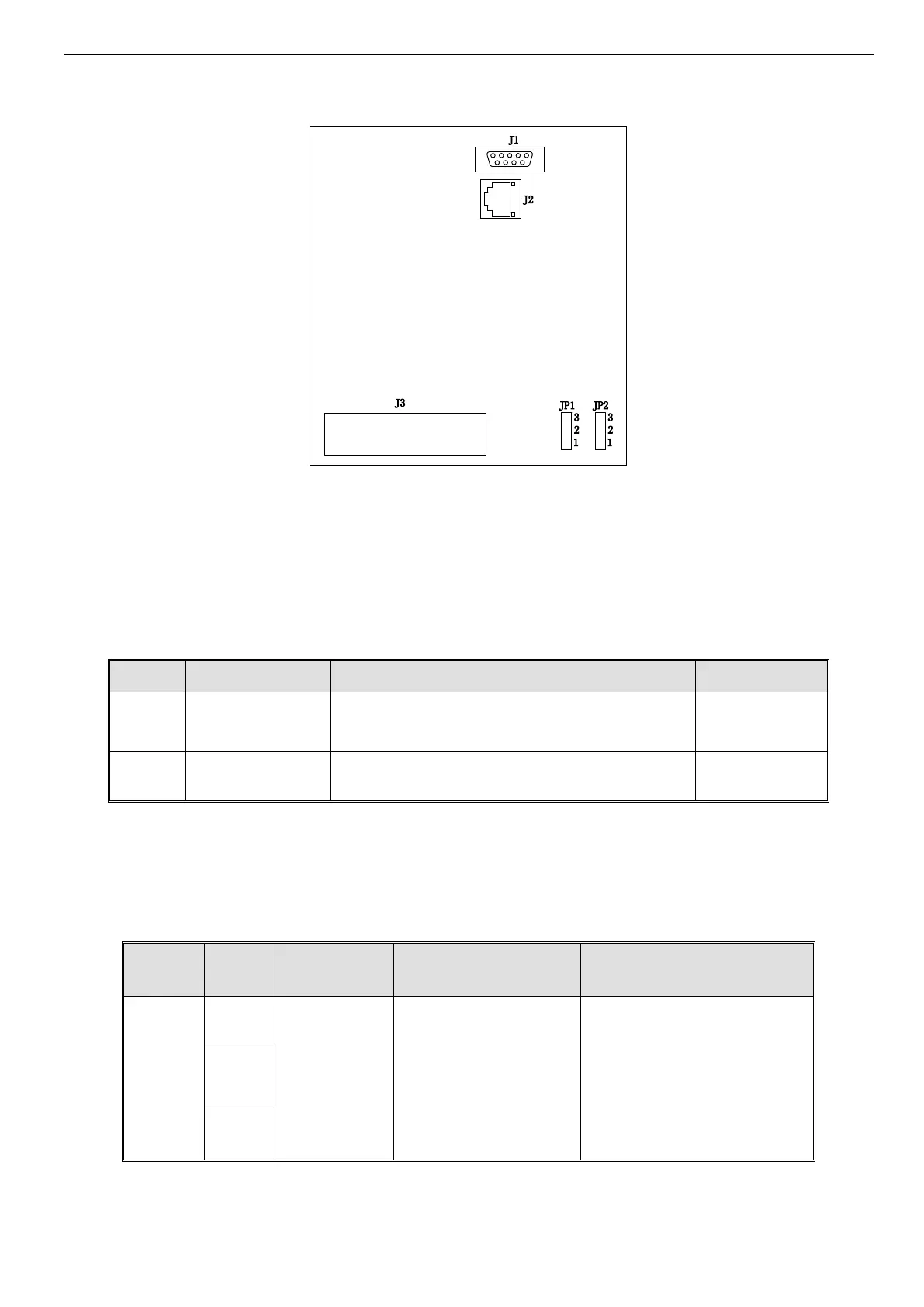
2.2~3.7KW VB5N(S) three phase inverter jumper location
Fig 2-4 (c) control panel terminal jumper location
The position of jumpers are shown in Fig. 2-4, the function of jumper terminals are shown in Table 2-3 and the function de-
scriptions of jumpers and their setting method are shown in Table2-2. Before running the inverter, make sure terminals wiring
and jumpers setting have been done, more than 1mm
2
cables are recommended to use. J1 is connector between operate panel
and CPU motherboard serial port. J2 is connector between operate panel and CPU motherboard RJ-45 Enthernet port. The
RJ-45 cable length cannot more than 3m.
Table 2-2 Function of jumpers
CI current/voltage input
modes selection
1-2 connect : V side: 0~10V voltage signal
2-3 connect : I side: 4~20mA current signal
Analog output terminal
AO output
1-2 connect: 0~10V, AO terminal outputs voltage signal
2-3 connect: 4~20mA, AO terminal outputs current signal
2-5-2.Terminals on control panel
1. Functions of CN3 terminal are shown in Table 2-3:
Table 2-3 Function of CN3
Multi-functional relay output
terminals. Please refer to func-
tion parameters P4.11 and de-
scription of output terminals
TA-TB: normal open
Contactor Capacity:
AC250V/2A (COSΦ=1)
AC250V/1A (COSΦ=0.4)
DC30V/1A
 Loading...