VB5N series inverter
73
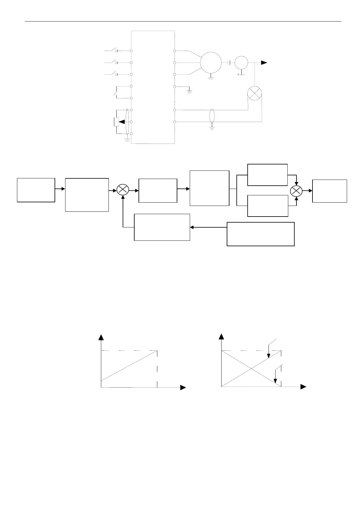
Fig.4-32 Analog feedback control system with internal PI
Principle diagram of inverter’s internal PI adjustor is shown below:
+ +
- +
Fig. 4-33 PI control principle diagram
The definition of close-loop value, feedback value, difference limit and proportion/integral parameter in Fig 4-33 are the
same to normal PI definition. Please refer to P7.01~P7.11. The relationship between preset value and expect feedback val-
ue is shown in Fig 4-34. The preset value is based on 10V; the feedback value is based on 20mA.
The aim of preset value adjustment and feedback value adjustment is to confirm the their relationship and size, as shown in
Fig.4-33.
In actual applications, if the motor speed increases with the preset value increasing, it is positive feature; if the motor speed
decreases with the preset value increasing, it is negative features.
The two close-loop features can be set via P7.14, as shown in Fig4-35.
Fig.4-34 Preset and Fig.4-35 Close-loop adjustment
expected feedback feature diagram
After confirming the system, the procedure of setting close-loop parameters is shown below:
(1) Confirm the close-loop setting and feedback channel (P7.01, P7.02).
(2) The relationship between close-loop setting and feedback value (P7.06~P7.09).
(3) Confirm the close-loop adjustment features (P7.14=1 negative function; 0 is positive function), as shown in Fig4-35.
(4) Set the close-loop preset frequency (P7.16~ P7.17).
(5) Set close-loop filter time, sampling cycle, difference limit and gain coefficient (P7.03, P7.04, P7.12, P7.13).
Preset value
adjustment
(P7.06,P7.08)
Close-loop
adjust feature
(P7.14)
Feedback value ad-
just (P7.07, P7.09)
Close-loop feedback value
 Loading...