12
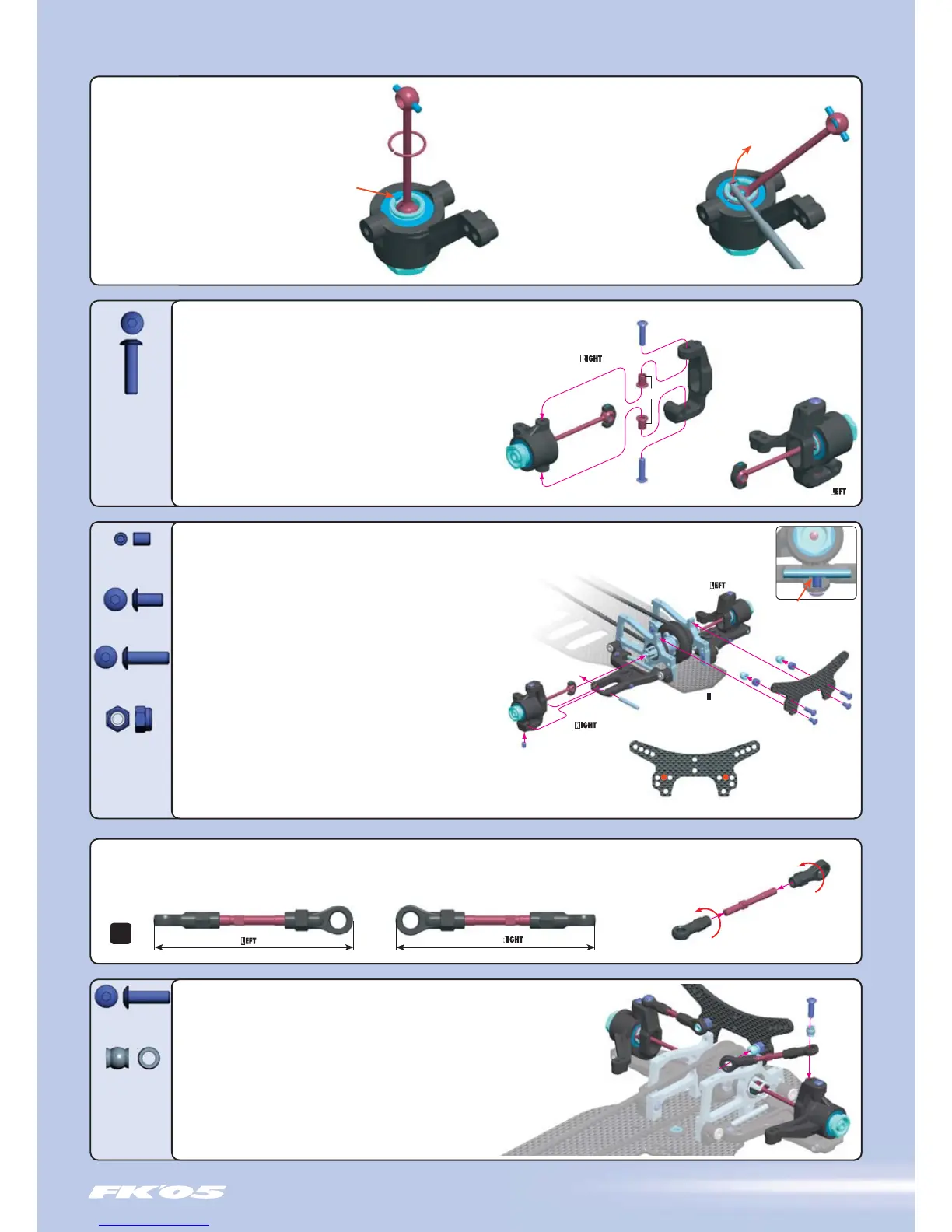
Install both front C-hub assemblies in the front lower arms by performing the
following steps.
1. Place the driveshaft plastic cap into the front axle outdrive slot. Insert the
C-hub assembly into the end of the front lower arm as shown. Align the hole
in the bottom of the C-hub and holes in the arm.
2. Slide a #307220 pivot pin through the aligned holes. Make sure the flat
spot on the pivot pin is toward the bottom.
3. Thread and tighten the #901304 (SB M3x4) set screw in the bottom
of the C-hub until it is tight on the pivot pin’s flat spot. Be very careful
not to overtighten the screw, as the threads may strip in the
composite C-hub. The C-hub assembly should move freely.
4. Mount the #302096 front shock tower to the front bulkheads
with two #902306 (SH M3x6) screws.
5. Mount two #960030 M3 nuts to the rear of the front
shock tower using two #902310 (SH M3x10) hex screws, using the
holes shown.
6. Mount two #303240 balls to the rear of the shock tower
on the same screws, against the M3 nuts.
FRONT SUSPENSION
902312
SH M3x12
902306
SH M3x6
902310
SH M3x10
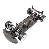
Assemble the TWO front C-hubs by performing the following steps.
1. Insert two #302290 bushings into the C-hub upper and lower holes.
Install the bushings from the inside of the C-hub as shown, with the flanges
facing into the C-hub.
2. Insert the steering block assembly into the C-hub, passing the driveshaft
through the oblong hole in the side of the C-hub. Insert the left steering
block assembly into C-hub marked L3, and insert the right steering
block assembly into C-hub marked R3.
3. Pass two #902312 (SH M3x12) screws through the bushings,
and thread into the top and bottom of the steering block.
The steering blocks should move freely.
INSTALLATION
Right C-Hub is marked ‘R3’
Left C-Hub is marked ‘L3’
REMOVAL
901304
SB M3x4
Assemble TWO front camber linkages by threading ball joints onto the ends of a #302630 turnbuckle as shown.
The ball joints should be perpendicular (90°) to each other. Adjust the linkages to a length of 49 mm, measured end-to-end.
Note: Each turnbuckle has a CCW thread on one end and a CW thread on the other end.
Groove
FRONT
INITIAL POSITION
307454
PB 5 mm
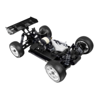
TO INSTALL A SNAP RING:
Place the hex portion of the wheel axle flat on a table.
Put one end of the snap ring into the groove on the
opposite side of the axle cutout, and use a slotted
screwdriver to work the clip into the groove.
TO REMOVE A SNAP RING:
Place the hex portion of the wheel axle flat
on a table. Insert a small screwdriver in the
axle cutout and pry it off, taking care not to
let it fly off the workbench.
Use proper eye protection.
DETAIL
Flat spot on pin
! Tighten very gently !
902310
SH M3x10
960030
N M3
49 mm
Assemble TWO front suspension arms by performing the following steps.
1. Place the assembled camber linkage between the front shock tower and C-hub.
2. Pass a #902310 (SH M3x10) screw downward through a #307454 pivot ball
and linkage ball joint, and thread into the hole in the top of the C-hub. Tighten
until the pivot ball snaps into the ball joint, and then tighten the whole assembly.
3. Snap the linkage ball joints onto the balls at the rear of the shock tower.
Check arms for free movement.
49 mm
1:1
 Loading...