2
KIT
302002
302002
904306
301164
904306
302002
302002
301112
301200
960030
904308
904306
FRONT
CONTENTS
0. KIT
2
1. BALL DIFFERENTIAL & FRONT MULTI-DIFF
3-4
2. REAR TRANSMISSION
5-6
3. REAR SUSPENSION
7-8
4. FRONT TRANSMISSION
9-10
5. FRONT SUSPENSION
11-12
6. STEERING
13-14
7. SHOCK ABSORBERS
15-16
8. REAR ASSEMBLY
17
FRONT ASSEMBLY
18
9. FINAL ASSEMBLY
19
ACCESSORY ASSEMBLY
20-21
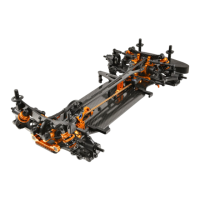
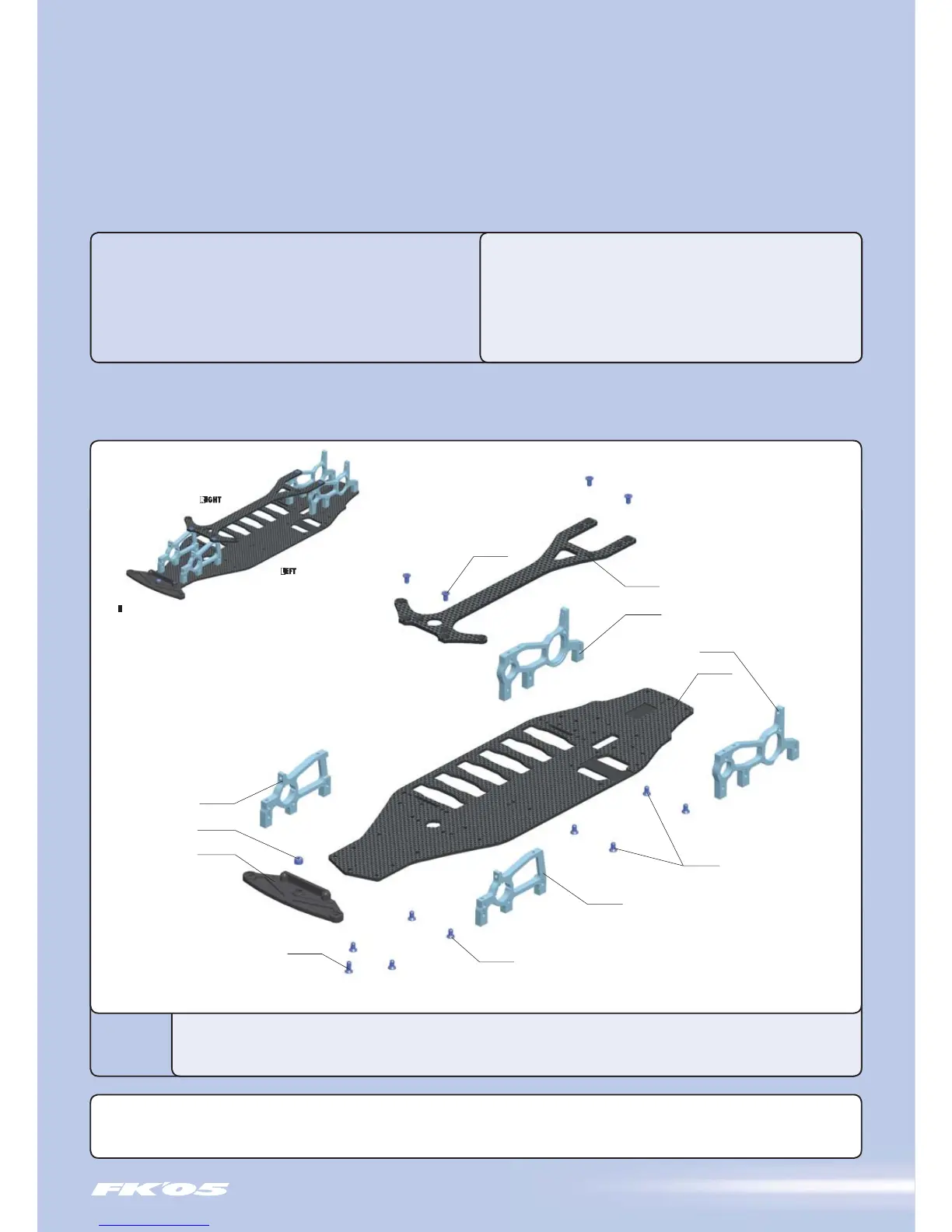
0. KIT (FACTORY PRE-ASSEMBLED)
KIT
BEFORE YOU START
At the beginning of each section is an exploded view of the parts to be
assembled. There is also a list of all the parts and part numbers that are
related to the assembly of that section.
The part descriptions are color-coded to make it easier for you to identify the
source of a part. Here are what the different colors mean:
STYLE A - indicates parts that are included in the bag marked
for the section.
STYLE B - indicates parts that were set aside in Section 0.
STYLE C
- indicates parts that are already assembled from
previous steps.
30 1112 6-CELL CHASSIS T1FK'05 - CNC MACHINED
30 1164 UPPER DECK T1FK'05 - CNC MACHINED
30 1200 COMPOSITE BUMPER
30 2002 ALU SUSP. ADJUSTABLE BULKHEADS T1FK'05 (4)
90 4306 HEX SCREW SFH M3x6 - SILVER (10)
90 4308 HEX SCREW SFH M3x8 - SILVER (10)
96 0030 NUT M3 (10)
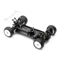
The XRAY T1FK'05 comes partially pre-assembled. Before starting assembly, disassemble the chassis parts, noting the position and orientation of the parts, particularly
the bulkheads. Keep the parts, including the screw hardware, close at hand. In the assembly steps that follow, each section begins with a parts list. Parts indicated
with style B are from the previously disassembled chassis parts in section 0.
 Loading...