981210
P 2x10
904306
SFH M3x6
965050
C5
309319
SHIM 3x7x2
902310
SH M3x10
902312
SH M3x12
Cutaway view
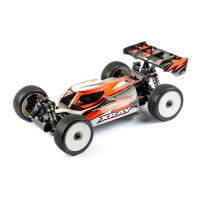
REAR TRANSMISSION
1. Attach #305784 spur gear to #305516 layshaft with three #902305
(SH M3x5) screws.
2. Press a #981210 (P 2x10) pin into the layshaft hole closest to the
spur gear.
3. Slide a 20T pulley onto the layshaft, and seat it over the pin.
4. Press the other #981210 (P 2x10) pin into the other layshaft hole.
5. Slide the other 20T pulley onto the layshaft, and seat it over the
second pin.
6. Snap a #965050 (C5) E-clip into the groove in the layshaft.
901408
SB M4x8
TOP
2.5 mm
3.0 mm
BOTTOM
901308
SB M3x8
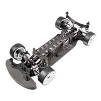
1. Thread a #901408 (SB M4x8) downstop adjustment screw
into the hole at the front of the rear lower arm as shown. The
screw must protrude 2.5 mm below the arm.
2. Thread a #901308 (SB M3x8) setscrew into the hole at
the rear of the rear lower arm as shown. The setscrew must
protrude 3.0 mm.
Repeat for the other arm, making sure to mirror
the screw placement.
3mm
1mm
2mm
clip/shim
DETAIL
DETAIL
902305
SH M3x5
Rear Toe-In Clip Settings
0mm clip = 0° rear toe-in
1mm clip = 1° rear toe-in
2mm clip = 2° rear toe-in
3mm clip = 3° rear toe-in
Use front MIDDLE hole
Use rear MIDDLE hole
Repeat to attach the other arm
to the other rear bulkhead.
1. Mount a lower suspension holder to the outside front of the rear bulkhead, using a #902310 (SH M3x10) screw and
#302032 alu nut. Use the MIDDLE hole as shown. Do not tighten the screw; leave the holder loose.
2. Slide a #307312 pivot pin through the holes in the rear lower arm.
3. Slide a 3mm shim onto the pin in front of the rear
lower arm.
4. Slide a 1mm shim onto the pin behind the rear lower arm.
5. Insert the front end of the pin in the front lower holder.
6. Mount a lower suspension holder on the rear end of the pin.
Attach the holder to the outside rear of the bulkhead using a
#902312 (SH M3x12) screw and #302032 alu nut. Use the MIDDLE hole
as shown. Do not tighten the screw; leave the holder loose.
7. Insert a 2mm clip on the screw between the rearmost
holder and the bulkhead. Tighten the screws.
When using wide (28mm) rear foam tires, cut material from both arms as
shown to mount shock lower joints to outer holes in arms. Counterbore the
holes for hex screws SB M3x8.
TIP
DETAIL
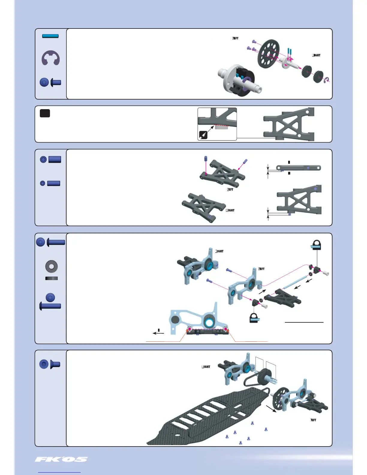
Cut away
FRONT
1. Mount the right rear bulkhead to the lower chassis using three
#904306 (SFH M3x6) screws.
2. Insert the left end of the #305516 layshaft into the small bearing
in the left rear bulkhead. Place the long front drive belt on the 20T
layshaft pulley closest to the spur gear.
3. Place the short rear belt onto the rear differential.
4. Insert the SHORT differential shaft into the ball-bearing in
the RIGHT bulkhead. Place the other end of the rear belt on the
layshaft’s other fixed pulley.
5. Slide the left rear bulkhead into position over the LONG left
differential shaft, and mount to the lower chassis using three
#904306 (SFH M3x6) screws.
 Loading...