x
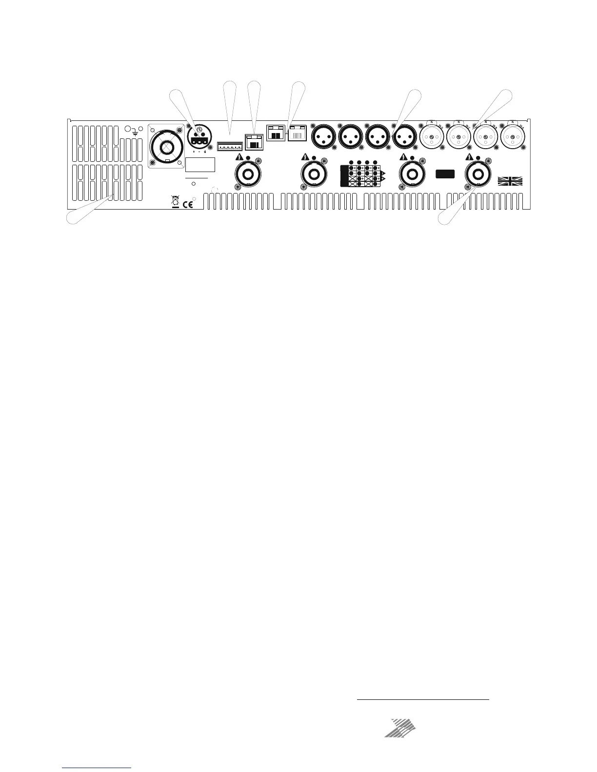
Operating Your Amplifier: Rear Panel Sockets and Switches
1: Fan outlet: The variable speed fans suck air in through the front vents and out through the
back of the amplifier. Please see maintenance on page 62 for recommendations on how to
clean this and the front foam sections.
2: Channel A output Speakon socket: Normal output is on pins 1+ hot, 1- cold. Channel B’s
output is also wired to this socket to enable a single NL4 to provide both channels and to
facilitate easier wiring in bridged mode. Channel B is wired pins 2+ hot, 2- cold. Similarly
channel C’s output Speakon socket carries Channel D’s output. Check the table on the rear
panel for details.
3: Input XLR sockets: Connect signal inputs to these sockets, wired pin 2 hot, 3 cold, 1
ground. For sensitivity and impedance of these inputs, please see the specifications on page
63. Inputs C & D may also be switched to AES digital inputs, each carrying a stereo AES
stream — channels A&B on socket C, channels C & D on socket D. This arrangement allows
an analogue stereo source to remain connected to sockets A & B for fallback purposes. To
select AES inputs please see the section on page 37.
4: Auxiliary output XLR sockets: These carry the four additional channels of separate DSP
processing — they are NOT just link outputs or a copy of the power amplifier channel’s
processed audio — they are fully independent.
5: Audio network connections
1
: Four additional inputs can be added to the available input
matrix via the optional Dante network card. This will also add four network audio outputs,
which can be chosen (in banks of four) from a variety of processing points within the
amplifier’s DSP structure. For more on this feature see the block diagram on page 21 and
set-up information from page 41.
6: Ethernet control port: Your amplifier may be remotely controlled by connecting it to a
computer via this standard Ethernet port connection. Please see the section starting on page
50 for how to use this feature. HINT: You can quickly check the amplifier’s IP address by
pressing ENTER + NEXT.
7: GPIO Port: Your amplifier has a pair of general purpose logic level input and outputs that
can be configured to recall memories, put the amplifier in standby, mute and control levels,
and also provide feedback about status.
8: RS485 Port: Your amplifier may also be controlled via an RS485 connection, and this port
may also be used to relay control data from the Ethernet port or the front panel USB port to
connect to further devices. Please see the remote control section on page 50 for more
information.
1
The audio network card is an option and may not be fitted to your amplifier.
All vents on front and rear of unit must not be obstructed.
Tous les p assag es sur avan t et arr i ère d e l'u n ité ne doi ven t p as êtr e obst rués.
SERIAL NO.
OUTPUT
Cl ass 3 Wi r ing
on O utp u t s
1 - AUDI O N ETW ORK - 2CONTROLGPIO PORT
1234 56
AUX 4 AUX 3 AUX 2 AUX 1
1: 0V
2/3: IN 1& 2
4/5: OUT 1&2
6: +5V
RS485
A
E
S
A
&
B
A
E
S
C
&
D
OUTPUTOUTPUTOUTPUT
OUTPUT WIRING
CONNECTORS
BR IDGE
1+
1-
2+
2-
PIN N UMBER
DESIGNE D AN D
MANUFAC TURED
IN ENGLAND
by
XTA Electronics Ltd.
and
MC Aud i o
2
MAINS SUPPLY
1
2
34
5
67
8
 Loading...