EasyManua.ls Logo

Yaesu VX-6R User Manual

Yaesu VX-6R
112 pages
To Next Page IconTo Next Page
To Previous Page IconTo Previous Page
Page #12 background imageLoading...
Page #12 background image
VX-6R/E OPERATING MANUAL10
INSTALLATION OF FBA-23 ALKALINE BATTER Y CASE
(
OPTION
)
The optional FBA-23 Battery Case allows receive monitoring using two “AA” size Alka-
line batteries. Alkaline batteries can also be used for transmission in an emergency, but
power output will only be selectable 300 mW and 50 mW, and battery life will be shortened
dramatically.
To Install Alkaline Batteries into the FBA-23
Slide the batteries into the FBA-23 as shown in the illustration,
with the Negative [–] side of the batteries touching the spring
connections inside the FBA-23.
Open the Battery Pack Latch on the bottom of the radio.
Install the FBA-23 as shown in the illustration, with the [+] side
facing the bottom of the transceiver.
Close the Battery Pack Latch on the bottom of the radio.
The FBA-23 does not provide connections for charging, since Alkaline cells cannot be
re-charged. Therefore, the NC-72/-PA-48, E-DC-5B, or E-DC-6 may safely be connected
to the EXT DC jack when the FBA-23 is installed.
1) The FBA-23 is designed for use only with AA-type Alkaline cells.
2) If you do not use the VX-6R/E for a long time, remove the Alkaline batteries
from the FBA-23, as battery leakage could cause damage to the FBA-23 and/or the
transceiver.
LOW BATTERY INDICATION
As your battery discharges during use, the voltage will gradually become lower. When
the battery voltage is becoming too low for reliable operation,
the “ ” icon will blink on the LCD display, indicating that the
battery pack must be recharged before further use.
Avoid recharging Lithium-Ion batteries before the “ ” indicator is observed, as
this can degrade the charge capacity of your Lithium-Ion battery pack.
INSTALLATION OF ACCESSORIES

Table of Contents

Other manuals for Yaesu VX-6R

Question and Answer IconNeed help?

Do you have a question about the Yaesu VX-6R and is the answer not in the manual?

Yaesu VX-6R Specifications

General IconGeneral
Frequency Range (Transmit)144-148 MHz, 222-225 MHz, 430-450 MHz
Waterproof RatingIPX7
Antenna ConnectorSMA
Frequency Range (Receive)0.5-999 MHz
ModesFM
Channels/Memory900
DisplayLCD
Receiver TypeSuperheterodyne

Summary

GENERAL DESCRIPTION

CONTROLS & CONNECTIONS (TOP & FRONT PANEL)

CONTROLS & CONNECTIONS (Keypad)

Keypad Function Descriptions

Detailed functions of each key on the transceiver keypad.

INSTALLATION OF ACCESSORIES

FNB-80LI Battery Pack Installation

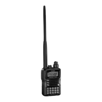
Steps for installing the FNB-80LI rechargeable battery pack.

OPERATION

Switching Power On and Off

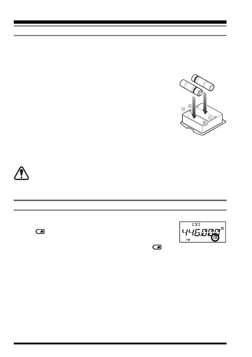
Steps to turn the transceiver on and off.

Squelch Adjustment

Procedure for setting the squelch level to reduce background noise.

Selecting the Operating Band

How to switch between different frequency bands supported by the radio.

Direct Keypad Frequency Entry

Method for entering frequencies directly using the numeric keypad.

Frequency Navigation

Explains methods for tuning frequencies using the DIAL knob or keypad.

Scanning

How to initiate frequency scanning to find active signals.

TRANSMISSION

Basic Transmission Steps

Basic steps for transmitting signals using the PTT switch.

Changing the Transmitter Power Level

How to select different transmit power output levels.

ADVANCED OPERATION

Keyboard Locking

How to lock the keypad and controls to prevent accidental changes.

RF Squelch

Setting squelch based on signal strength (S-meter level).

REPEATER OPERATION

Repeater Shifts

Explains default repeater shift values for different bands.

Manual Repeater Shift Activation

Manually setting the repeater shift direction (plus, minus, simplex).

Automatic Repeater Shift (ARS)

How to automatically apply repeater shifts based on band.

CTCSS/DCS OPERATION

CTCSS Operation

Setting up CTCSS tones for repeater access and selective calling.

DCS Operation

Setting up Digital Coded Squelch (DCS) for enhanced selective calling.

MEMORY MODE

MEMORY MODE (REGULAR MEMORY CHANNEL)

Memory Storage

Procedure for storing frequencies and settings into memory.

Storing Independent Transmit Frequencies (“Odd Splits”)

How to store separate transmit and receive frequencies for repeaters.

Memory Bank Operation

Organizing memories into 24 banks for easier management.

Memory Recall

How to retrieve stored frequencies from memory.

MEMORY MODE (REGULAR MEMORY CHANNELS)

Direct Memory Recall Channel

Direct access to up to ten favorite frequencies via numeric keys.

SCANNING

Setting the Scan-Resume Technique

Configuring how the scanner resumes after finding a signal.

VFO Scanning

Scanning across frequencies in VFO mode with adjustable bandwidth.

Memory Scanning

Scanning through stored memory channels using various modes.

Preferential Memory Scan

Setting up a list of preferred channels for scanning.

Programmable (Band Limit) Memory Scan (PMS)

Scanning within user-defined sub-band limits.

“Priority Channel” Scanning (Dual Watch)

Checking a priority channel periodically while operating on another.

How to Skip (Omit) a Frequency during VFO Scan

Storing frequencies to be skipped during VFO scanning.

How to Skip (Omit) a Channel during Memory Scan Operation

Marking memory channels to be skipped during memory scanning.

SMART SEARCH OPERATION

Setting the Smart Search Mode

Selecting between single sweep or continuous sweep modes.

EPCS (ENHANCED PAGING & CODE SQUELCH)

Storing the CTCSS Tone Pairs for EPCS Operation

Setting up paired CTCSS tones for paging and selective calling.

Activating the Enhanced Paging & Code Squelch System

Enabling the EPCS feature for paging and selective calls.

EMERGENCY FEATURE

Emergency Channel Operation

Using the dedicated emergency channel and its features.

Selecting the EAI mode and its Transmit Time

Configuring EAI mode (interval/continuous) and transmit time.

To Locate an Unresponsive Operator Using the EAI feature

Using EAI to find an incapacitated operator.

Emergency Automatic ID (EAI) Feature

Automatically transmitting callsign in emergencies.

Activating the EAI feature

Steps to enable the Emergency Automatic ID feature.

ARTS™ (AUTOMATIC RANGE TRANSPONDER SYSTEM)

Basic ARTS™ Setup and Operation

Setting up and using the ARTS™ system for range confirmation.

INTERNET CONNECTION FEATURE

SRG (“SISTER RADIO GROUP”) MODE

Activating the Internet Connection feature for WIRES™ nodes.

FRG (“FRIENDLY RADIO GROUP”) MODE

Accessing Internet Link Systems using DTMF strings.

DTMF OPERATION

MISCELLANEOUS SETTINGS

RESET PROCEDURES

Microprocessor Resetting

Restoring transceiver to factory defaults by resetting the microprocessor.

Set Mode Resetting

Resetting Set Mode items to their factory defaults.

SET (MENU) MODE

Set Mode Item [EAI]

Enabling/Disabling the Emergency Automatic ID (EAI) Feature.

Set Mode Item [EAI.TMR]

Setting EAI operating mode and transmit time.

Set Mode Item [PAGER]

Enabling/disabling Enhanced CTCSS Paging & Code Squelch.

Related product manuals