Panel and Connector Arrangement
13
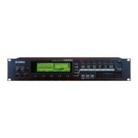
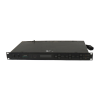
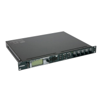
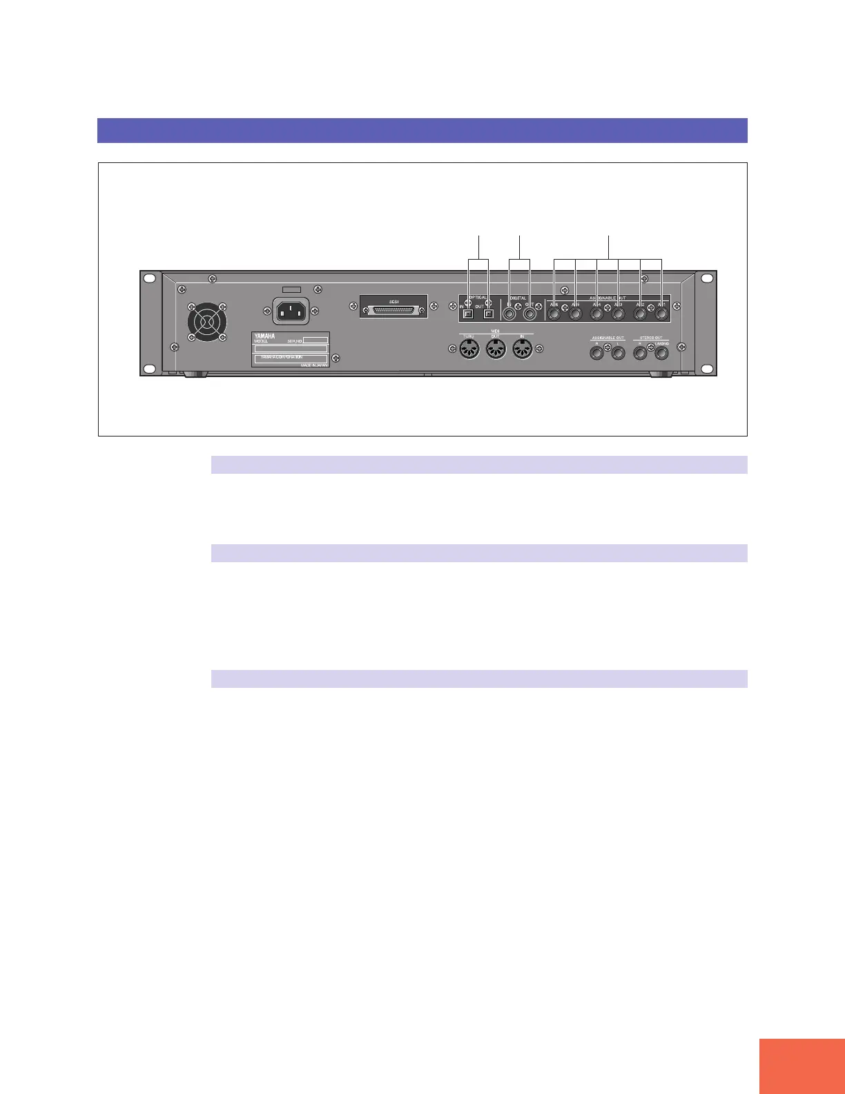
Rear Panel (with optional AIEB1 board installed)
(1) (2) (3)
(1) OPTICAL IN, OUT connectors
Use these connectors to input or output digital signals over optical-fiber cable. You can
use the OPTICAL IN to record a digital signal of frequency 48kHz, 44.1kHz, or 32kHz.
The OPTICAL OUT connector outputs a digital signal of frequency 44.1kHz.
(2) DIGITAL IN, OUT connectors
Use these connectors to input or output digital signals over coaxial (RCA-pin) cable. The
digital signal format is CD/DAT (S/P DIF).
You can use the DIGITAL IN connector to record a digital signal of frequency 48kHz,
44.1kHz, or 32kHz. The DIGITAL OUT connector outputs a digital signal of frequency
44.1kHz.
(3) ASSIGNABLE OUT jacks (AS1 to AS6)
Additional analog output jacks. Each pair (1&2, 3&4, 5&6) operates independently of all
other outputs on the A3000. You can use these jacks to output the sound of one or more
selected samples, or to output the signal supplied through the front panel’s analog in-
put connectors (☞134, 176). You may also set them so that they output the same signal
as the STEREO OUT jacks (☞299).
 Loading...