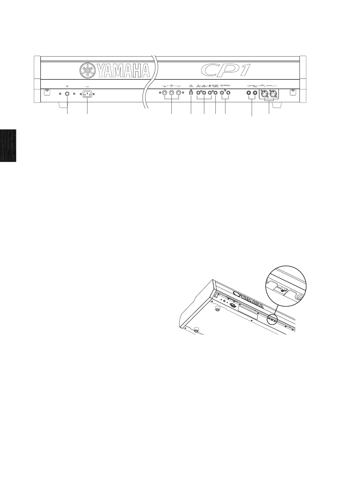
Rear Panel
18 CP1 Owner’s Manual
Component Names & Functions
Rear Panel
1 [P] (power) switch (see page 13)
Use this button to turn the CP1 on and off.
2 [AC IN] socket (see page 10)
Use this socket to connect the power cord. Note that only the
power cord provided with the CP1 should be used to supply
power.
3 MIDI [IN], [OUT], and [THRU] connectors (see
page 35)
Use the three MIDI connectors to link up your CP1 with other
MIDI devices.
4 [USB TO HOST] port (see page 36)
Use this port to connect the CP1 to a computer using a USB
cable.
5 [SUSTAIN], [SOSTENUTO], and [SOFT] foot-
switch jacks (see page 30)
These jacks are used to connect the pedal unit that comes
with your CP1. An optional FC3, foot pedal or an optional
FC4, or FC5 foot switch can also be connected via the
[SUSTAIN] jack for use as a dedicated sustain pedal.
Meanwhile, optional FC4 and FC5 foot switches can be
connected via the [SOSTENUTO] and [SOFT] jacks in order
to perform a range of freely assignable functions.
6 [ASSIGNABLE] foot-switch jack (see page 12)
Use this jack to connect an optional FC4 or FC5 foot switch
in order to perform a range of freely assignable functions.
7 [1] and [2] foot-controller jacks (see page 12)
Use these two jacks to connect optional FC7 and FC9 foot
controllers in order to perform a range of freely assignable
functions.
8 Unbalanced [L/MONO] and [R] output jacks
(see page 11)
These two 1/4" mono phone jacks are used to output
unbalanced stereo signals. Alternatively, if mono output is
required, only the [L/MONO] jack should be connected.
Each jack’s nominal signal level is +4 dB.
9 Balanced [L] and [R] output connectors (see
page 11)
These XLR-type connectors are used to output balanced
stereo signals to mixers and the like. This type of connector
protects signals from interference and has an extremely
sturdy design. It also features a locking mechanism to
prevent cables from being accidentally disconnected.
Accordingly, the XLR connector is often used in professional
environments that demand a high level of reliability. Each
connector’s nominal signal level is +4 dB.
) [LIGHT] switch
Use this switch to turn the Yamaha logo lamp on or off and to
set its brightness. When positioned fully to the left, the lamp
will be turned off; when moved to the right, the switch will
click and the lamp will light up. As the switch is then moved
further towards the right, it selects three increasing levels of
brightness.
)
 Loading...