EasyManuals Logo

Yamaha F250 User Manual

Yamaha F250
124 pages
To Next Page IconTo Next Page
To Previous Page IconTo Previous Page
Page #35 background imageLoading...
Page #35 background image
28
Components
EMU2579Z
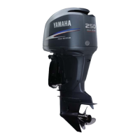
Components diagram
TIP:
* May not be exactly as shown; also may not be included as standard equipment on all mod-
els (order from dealer).
1
3
5
6
7
8
9
9
10
9
11
11
8
4
2
ZMU07139
1. Top cowling
2. Idle hole
3. Anti-cavitation plate
4. Trim tab (anode)
5. Propeller*
6. Cooling water inlet
7. Clamp bracket
8. Tilt support lever
9. Cowling lock lever
10. Flushing device
11. Power trim and tilt switch
6CE-9-36-1E0.book 28 ページ 2014年11月28日 金曜日 午後2時55分
©2019 Yamaha Motor Corporation, U.S.A.

Table of Contents

Other manuals for Yamaha F250

Questions and Answers:

Question and Answer IconNeed help?

Do you have a question about the Yamaha F250 and is the answer not in the manual?

Yamaha F250 Specifications

General IconGeneral
Prop Shaft Horsepower250 hp
Full Throttle RPM Range5000 - 6000 rpm
Gear Ratio1.75:1
Starting SystemElectric
Displacement4169cc
Bore x Stroke96 x 96 mm
Fuel Induction SystemEFI (Electronic Fuel Injection)
Ignition SystemTCI (Transistor Controlled Ignition)
Alternator Output50 amps
SteeringRemote
Shaft Length25 in
Weight253 kg (557 lbs) - F250XCA
Recommended FuelRegular Unleaded (Minimum Octane 87)

Related product manuals