Basic components
18
When constant speed is desired, tighten the
adjuster to maintain the desired throttle set-
ting.
EMU25990
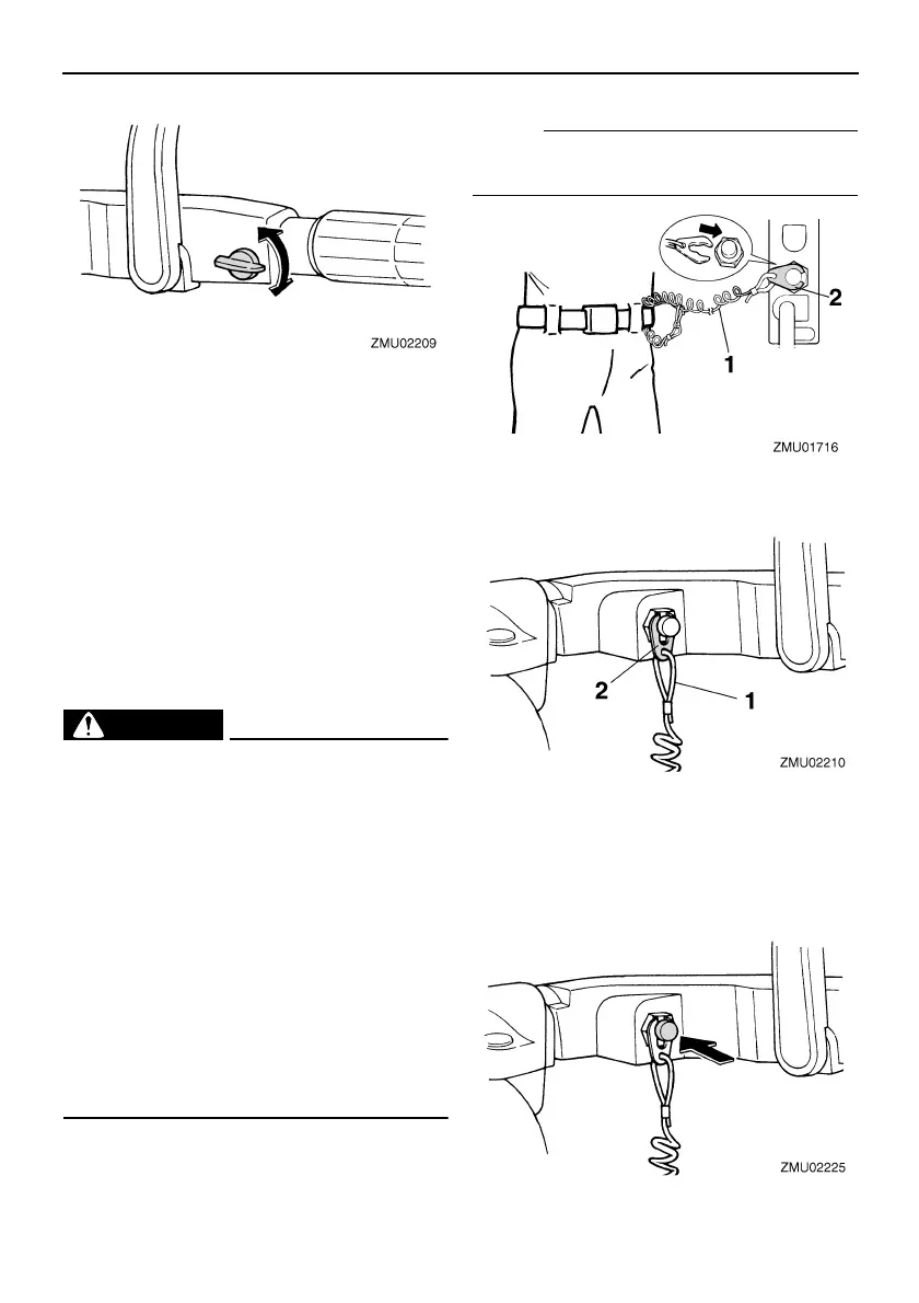
Engine stop lanyard switch
The lock plate must be attached to the engine
stop switch for the engine to run. The lanyard
should be attached to a secure place on the
operator’s clothing, or arm or leg. Should the
operator fall overboard or leave the helm, the
lanyard will pull out the lock plate, stopping ig-
nition to the engine. This will prevent the boat
from running away under power.
WARNING
EWM00120
● Attach the engine stop switch lanyard to
a secure place on your clothing, or your
arm or leg while operating.
● Do not attach the lanyard to clothing
that could tear loose. Do not route the
lanyard where it could become entan-
gled, preventing it from functioning.
● Avoid accidentally pulling the lanyard
during normal operation. Loss of engine
power means the loss of most steering
control. Also, without engine power, the
boat could slow rapidly. This could
cause people and objects in the boat to
be thrown forward.
NOTE:
The engine cannot be started with the lock
plate removed.
EMU26001
Engine stop button
To open the ignition circuit and stop the en-
gine, push this button.
1. Lanyard
2. Lock plate
1. Lanyard
2. Lock plate
U60R13E0.book Page 18 Thursday, April 6, 2006 10:29 AM

 Loading...