Operation
29
3. If a steering friction adjuster is provided
on your outboard motor, securely attach
the fuel line to the fuel line clamp.
NOTE:
During engine operation place the tank hori-
zontally, otherwise fuel cannot be drawn from
the fuel tank.
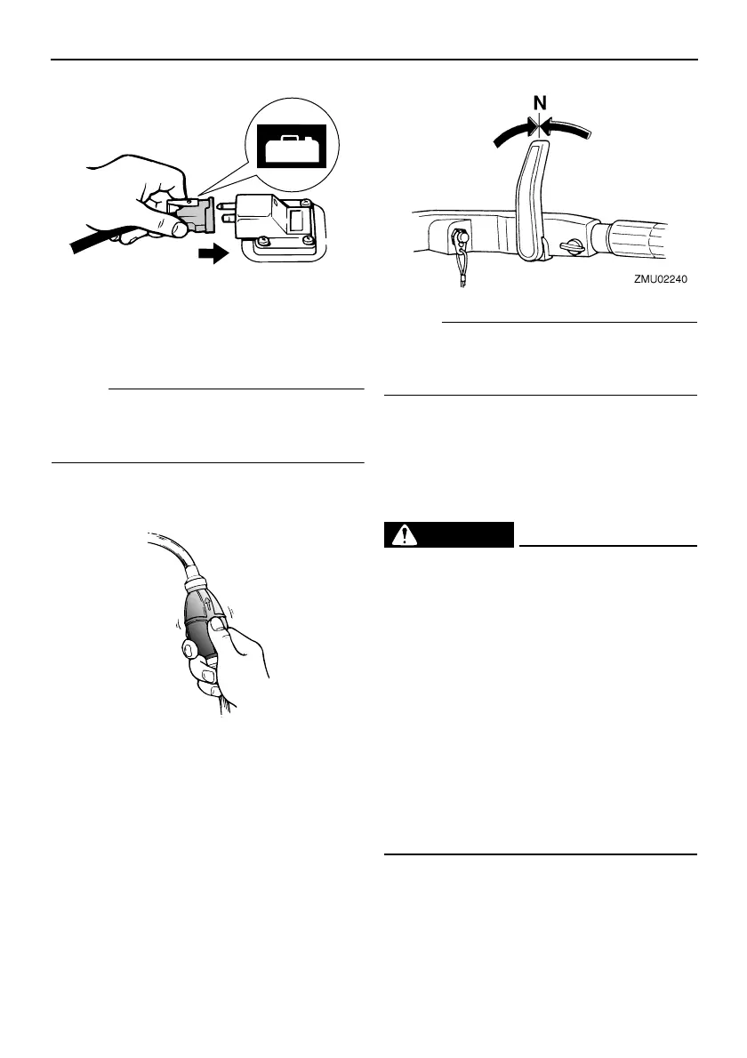
4. Squeeze the primer pump with the outlet
end up until you feel it become firm.
EMU27490
Starting engine
EMU27505
Manual start models (tiller control)
1. Place the gear shift lever in neutral.
NOTE:
The start-in-gear protection device prevents
the engine from starting except when in neu-
tral.
2. Attach the engine stop switch lanyard to
a secure place on your clothing, or your
arm or leg. Then install the lock plate on
the other end of the lanyard into the en-
gine stop switch.
WARNING
EWM00120
● Attach the engine stop switch lanyard to
a secure place on your clothing, or your
arm or leg while operating.
● Do not attach the lanyard to clothing
that could tear loose. Do not route the
lanyard where it could become entan-
gled, preventing it from functioning.
● Avoid accidentally pulling the lanyard
during normal operation. Loss of engine
power means the loss of most steering
control. Also, without engine power, the
boat could slow rapidly. This could
cause people and objects in the boat to
be thrown forward.
ZMU02024
ZMU02025
U60R13E0.book Page 29 Thursday, April 6, 2006 10:29 AM

 Loading...