7-2
Outboard Rigging Guide - 2001
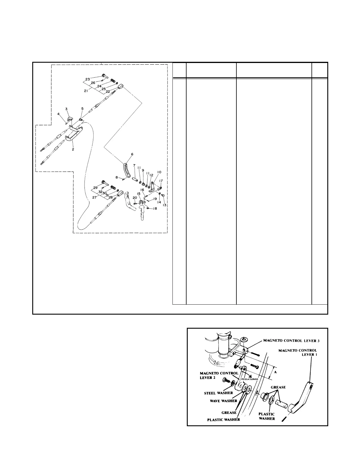
6/8HP REMOTE CONTROL ATTACHMENT KIT (6G1-48501-50-00)
REF
NO PART NUMBER DESCRIPTION QTY.
1 Remote Control Attach. Kit 1
2 6G1-48531-50-00 • Remote Control Bracket 1 1
3 682-48538-50-00 • Cable Clamp 2
4 91690-30012-00 • Spring Pin 2
5 90105-06M23-00 • Bolt 2
6 6G1-41631-50-EK • Magneto Control Lever 1 1
7 6G1-41635-50-00 • Link Connecting Shaft 1
8 91690-400160-00 • Spring Pin 1
9 90386-10009-00 • Bushing 1
10 6G1-41632-50-94 • Magneto Control Lever 2 1
11 90202-10024-00 • Plate Washer 2
12 90206-10M12-00 • Wave Washer 1
13 97313-05014-00 • Bolt 1
14 92990-05600-00 • Washer 1
15 6G1-41633-50-94 • Magneto Control Lever 3 1
16 6G1-41238-50-00 • Link Joint 1 1
17 6H1-41237-00-00 • Link Joint 2 1
18 90202-05088-00 • Washer 1
19 91490-25015-00 • Cotter Pin 1
20 97780-50520-00 • Screw 1
21 682-48340-50-00 • Throttle Cable End Assembly 1
22 682-48344-50-00 • Remote Control Cable End 1 1
23 617-48361-90-00 • Cable Hook 1
24 90501-10264-00 • Spring 1
25 92990-08600-00 • Washer 1
26 91690-30012-00 • Spring Pin 1
27 682-48330-50-00 • Shift Cable End Assembly 1
28 682-48346-50-00 • Remote Control Cable End 1
29 617-48331-91-00 • Cable Hook 1
30 90501-10071-00 • Spring 1
31 92990-08600-00 • Washer 1
32 91690-30012-00 • Spring Pin 1
• Component parts
Installation
1. Install the magneto control lever 1 and the
magneto control lever 2 through the bottom
cowling.
NOTE:Be sure to grease all the washers, bush-
ings and the shaft as shown. Use Yamaha Marine
Grease.
2. Install the magneto control lever 3 onto the
magneto control shaft as shown in the pre-
ceding illustration.
3. Place the throttle grip in the fully closed posi-
tion. Place the magneto control lever 2 in the
fully closed position so it contacts the bottom
stopper.
 Loading...