10B-29
Outboard Rigging Guide - 2001
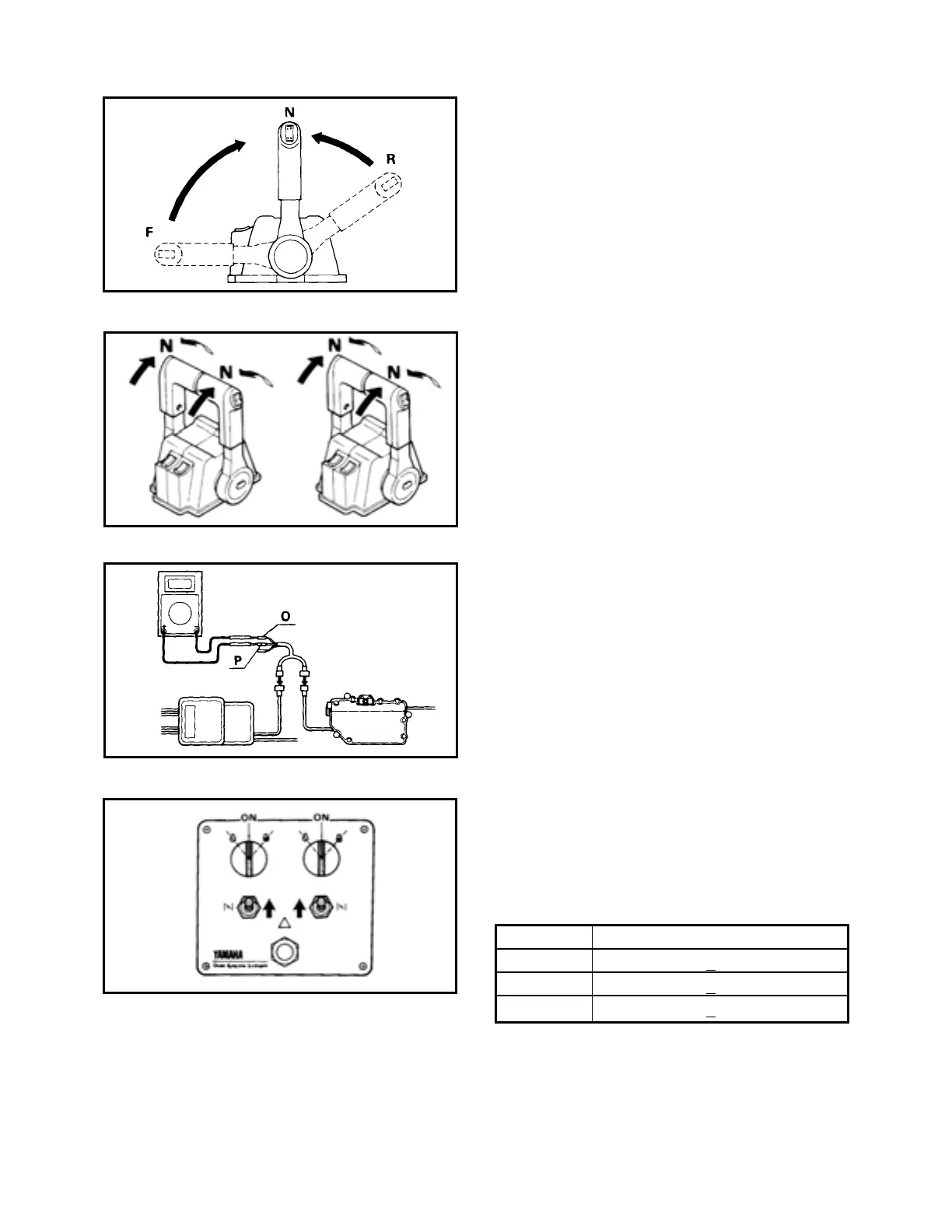
3) Place the remote control lever in neutral
and turn the main switch to start to check
that the engine is started.
In case the engine is not started, refer to
the SHIFT VOLTAGE ADJUSTMENT. Page
10B-29.
SHIFT VOLTAGE ADJUSTMENT
In case the engine is started at either forward
or reverse shift through the cable lengths are
within the specifications, check the shift volt-
age by using the following procedure.
1) Connect the throttle sensor adjusting lead,
special tool No. YB-06443 in between the
two sensors on the junction unit and the
actuator.
2) Turn the main switch to ON and check the
voltage between the sensors according to
the following specifications with the remote
control lever at neutral, forward and
reverse positions.
If any of the voltages is out of the specifica-
tions, adjust the location of the shift rack in the
junction unit.
Shift Specifications in V
Neutral 2.45 + 0.25
Forward 3.95 + 0.25
Reverse 0.95 +
0.25
 Loading...