<3. INSTALLATION>
3-1
IM 01E30D01-01EN
3. INSTALLATION
3.1 Piping Design Precautions
WARNING
Installationofthemagneticowmetermust
be performed by expert engineer or skilled
personnel. No operator shall be permitted to
perform procedures relating to installation.
IMPORTANT
Design piping correctly, read the following to
preventdamagetoowtubesandtoassure
accurate measuring.
(1) Location
IMPORTANT
Installtheowmeterinalocationwhereitis
not exposed to direct sunlight. The minimum
ambient temperature is limited by the minimum
uidtemperatureoftheowtube.Formore
information,readChapter12.Theowmeter
may be used in an ambient humidity where
the relative humidity ranges from 0 to 100%.
However, avoid long-term continuous operation
at relative humidity above 95%.
(2) Noise Avoidance
IMPORTANT
Theowmetershouldbeinstalledawayfrom
electrical motors, transformers, inverters
and other power sources in order to avoid
interference with measurement.
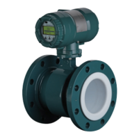
(3) Required Lengths of Straight Runs
To maintain accurate measurement, read JIS B
7554 which explains the requirements for upstream
pipingconditionsofmagneticowmeter.
The piping conditions we recommend as shown in
Figure 3.1.1 are based on JIS B7554 and on our
piping condition test data.
This is not always enough when the piping line
incorporates multiple conditions at the same time.
Wheninstallingtwoormoremagneticowmeteron
a single pipe, provide a run of at least 5D between
them.
Gate valve
fully open
Reducer
pipe
5 D or more
2 D or more
2 D or more
2 D or more
10 D or more
10 D or more
5 D or more
5 D or more
0 is allowable
0 is allowable
0 is allowable
0 is allowable
F0301.ai
Tee
90-degree bent
Various valves
Expander
pipe
Figure 3.1.1 Required Lengths of Straight Runs
*1: Do not install anything in the vicinity that may interfere
withthemagneticeld,inducedsignalvoltages,orow
velocitydistributionsoftheowmeter.
*2: A straight run may not be required on the downstream
sideoftheowmeter.However,ifadownstreamvalve
orotherttingcausesirregularityordeviationinows,
provide a straight run of 2D to 3D on the downstream side.
*3: Highly recommend to mount valves on the downstream
sidesothatdeviatedowsdonotoccurintheowtube
and to avoid startup from an empty condition.
*4: In case the piping conditions are compounded, install
on the straight pipe section where the upstream part is
sufcientlyrectied.
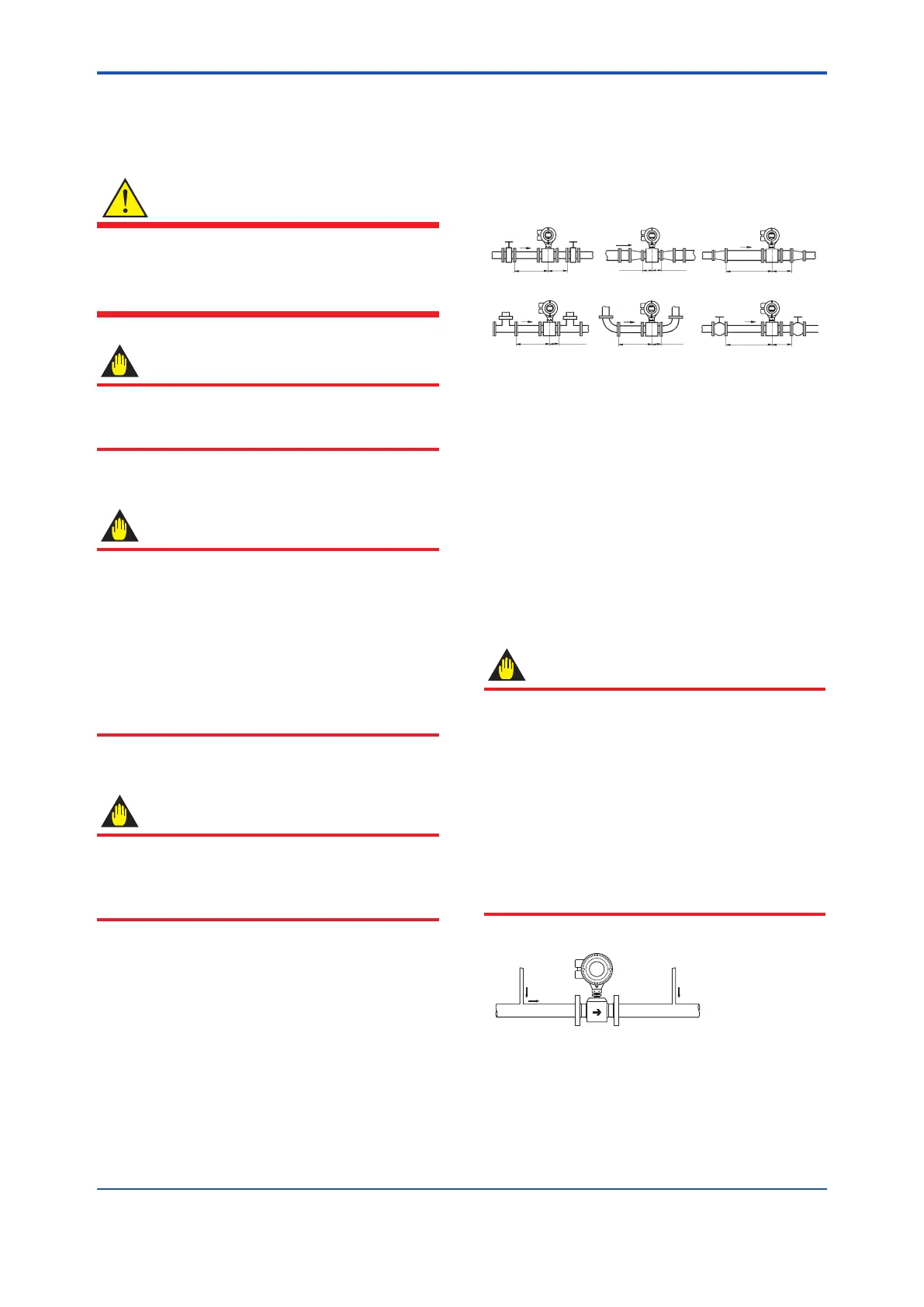
(4) Maintaining Stable Fluid Conductivity
IMPORTANT
Donotinstalltheowmeterwhereuid
conductivity tends to become uneven. If
chemicals are fed near the upstream side of a
magneticowmeter,theymayaffecttheow
rate’s indications. To avoid this situation, it is
recommended that the chemical feed ports be
locatedonthedownstreamsideoftheowmeter.
If it is unavoidable that chemicals must be fed
ontheupstreamside,provideasufcientlength
of straight run (approximately 50D or more) to
ensurethepropermixtureofuids.
F0302.EPS
(Incorrect)
Upstream side
(Correct)
Downstream side
Figure 3.1.2 Chemical Injection

 Loading...