<11. MAINTENANCE>
11-9
IM 01E30D01-01EN
11.5 Regular Inspection Items
(1) Inspectionofmoisture-proonginsidethe
terminal box: Once/year
(2) Retightening of piping joint screws: About twice/
year
(3) Inspection of electrodes and lining (in case of
adhesiveand/orabrasiveuids,etc.)
Determine the period of regular inspection as
necessary.
11.6 Insulation Resistance Test,
Dielectric Strength Test
NOTE
Note the following precautions when conducting
the insulation resistance test and dielectric
strength test.
(1) Conduct these tests as necessary minimum.
Applying the test voltage may deteriorate the
insulation and safety of the instrument, even
if the overvoltage is far below the insulation
breakdown level.
(2) The voltage for the insulation resistance test
must be 500 V DC or less (100 V DC or less
for the optional code A). The voltage for the
dielectric strength test must be 500 V AC or
less (100 V AC or less for the optional code A).
(3) The test procedures are as follows. Be sure
to disconnect all the wiring before the tests.
11.6.1
Procedure of Insulation Resistance test
(1) Individually, short-circuit the power supply
terminals (SUPPLY+ and SUPPLY-) and digital
output terminals (DO+ and DO-), and connect
the insulation resistance tester (Power OFF) to
the functional grounding terminal..
The polarity between the power supply and
the current output terminal or the digital output
terminal must become a positive pole.
(2) ApplytheDCvoltagespeciedinTable11.6.1
between above-mentioned terminal and the
functional grounding terminal.
The voltage impression time should be a period
whilethetestresultcouldreachfulllingthe
standard.
(3) Afterinspection,insertaresister(100kΩ,
1/2W) between the terminals and discharge for
approximately one second. Never touch the
terminals with bare hands during discharge.
Furthermore, never short-discharge without
inserting a resister.
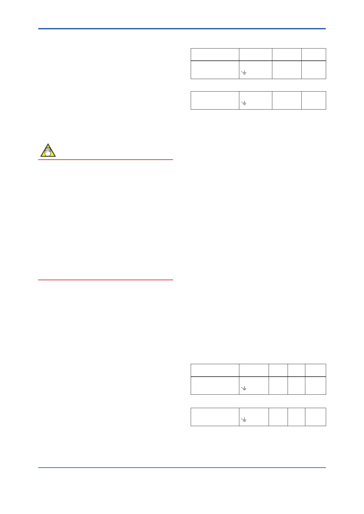
Table 11.6.1 Test terminal for insulation resistance
test
Inspection location Terminal
Test
voltage
Standard
Power Supply/Digital
Output - Functional
Grounding
SUPPLY/DO
500 V DC
100MΩ
or more
When the optional code A is selected (with the lightning
protector), values are as follows.
Power Supply/Digital
Output - Functional
Grounding
SUPPLY/DO
100 V DC
20MΩ
or more
11.6.2 Procedure of Dielectric Strength Test
(1) Individually, short-circuit the power supply
terminals (SUPPLY+ and SUPPLY-) and digital
output terminals (DO+ and DO-), and connect
the dielectric strength tester (Power OFF)
to the functional grounding terminal. Set the
current limitation value as 20 mA in the tester.
The polarity between the power supply and
the current output terminal or the digital output
terminal must become a positive pole.
(2) ApplytheACvoltagespeciedinTable11.6.2,
which approximates a sinusoidal wave form (50
Hz or 60 Hz), between the above mentioned
terminal and the functional grounding terminal.
The AC voltage should be given from 0V to
theinspectionvoltagespeciedinTable11.6.2
gradually.
(3) Keep one minute under the inspection voltage,
andconrmfulllingthestandardorlessofthe
tester.
(4) Decrease the voltage slowly so as not to
generate the voltage serge after the test ends.
(5) Afterinspection,insertaresister(100kΩ,1/2W)
between the terminals and discharge for
approximately one second. Never touch the
terminals with bare hands during discharge.
Furthermore, never short-discharge without
inserting a resister.
Table 11.6.2 Test terminal for dielectric strength test
Inspection location Terminal
Test
voltage
Test
time
Standard
Power Supply/Digital
Output - Functional
Grounding
SUPPLY/DO
500 V
AC
1 min.
25 mA
or less
When the optional code A is selected (with the lightning
protector), values are as follows.
Power Supply/Digital
Output - Functional
Grounding
SUPPLY/DO
100 V
AC
1 min.
6 mA
or less

 Loading...