036-21323-002-C-0206
12 Unitary Products Group
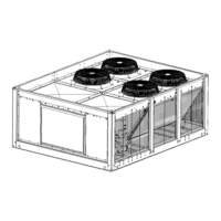
TABLE 13: SUCTION LINES
1
2
Model Designation
Nominal
Capacity
(Tons)
Refrigerant
Flow
Rate
3
(Lbs./
Min.)
Copper Tub-
ing (Inches,
O.D.)
Refrigerant
Gas Velocity
(Ft./Min.)
Friction Loss
4
5
(PSI/100 Ft.)
HL-15 4-Pipe System
System # 1 7 1/2 24.6
1 1/8 2050 4.3
1 3/8 1680 1.6
1 5/8 1140 0.7
System # 2 7 1/2 24.6
1 1/8 2050 4.3
1 3/8 1680 1.6
1 5/8 1140 0.7
HL-20 4-Pipe System
System # 1 10 32.5
1 1/8 3500 8.0
1 3/8 2280 2.8
1 5/8 1560 1.2
System # 2 10 32.5
1 1/8 3500 8.0
1 3/8 2280 2.8
1 5/8 1560 1.2
1. All horizontal suction lines should be pitched at least 1 inch every 20 feet in the direction of the refrigerant flow to aid the return of
oil to the compressor.
2. Every vertical suction riser greater than 25 feet in height should have a “P” trap at the bottom to facilitate the return of oil to the
compressor. Use short radius fittings for these traps.
3. Based on Refrigerant-22 at the nominal capacity of the condensing unit, a saturated suction temperature of 45°F and a liquid tem-
perature of 110°F.
4. Although suction lines should be sized for a friction loss equivalent to a 2°F change in saturation temperature (or approximately
3psi), sizing the lines for the proper return of oil is more important.
5. These friction losses do not include any allowances for valves or fittings.
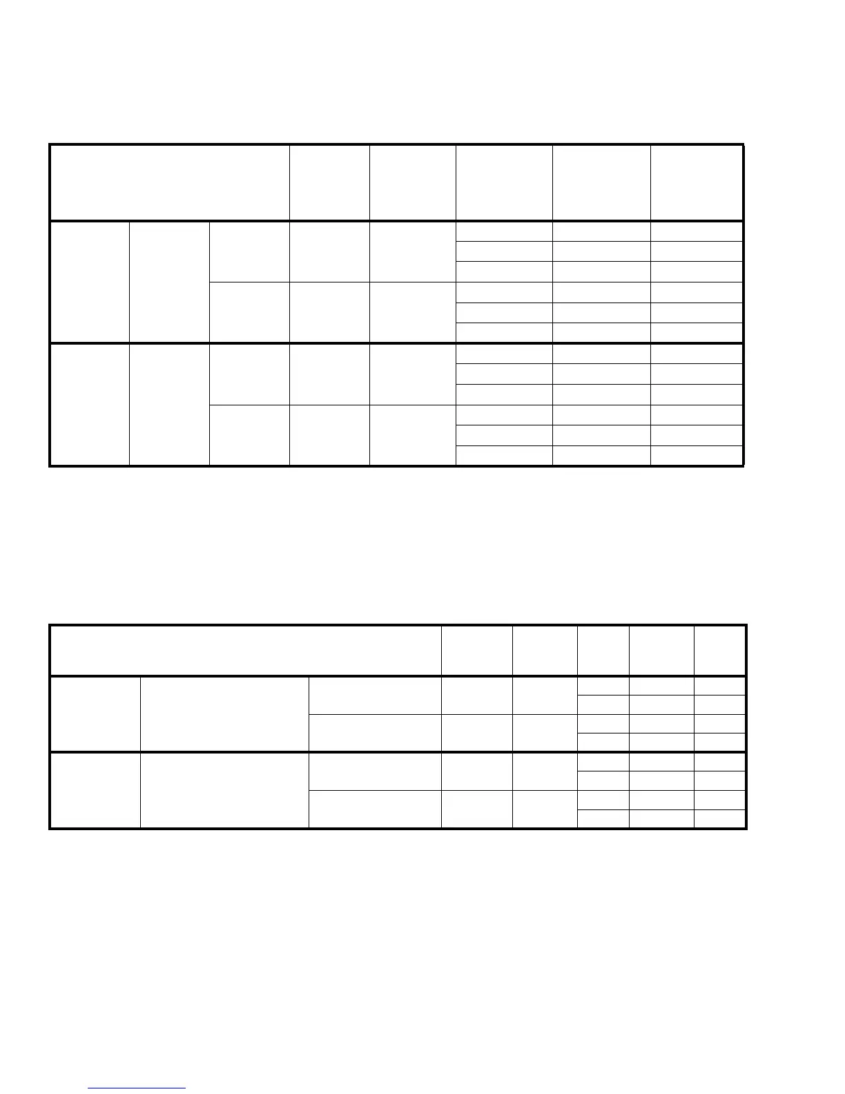
TABLE 14: LIQUID LINES
Model Designation
Nominal
Capacity
(Tons)
Refrigerant
Flow Rate
1
(Lbs./Min.)
Copper
Tubing
(Inches,
O.D.)
Friction
Loss
2
3
(PSI/100 Ft.)
Vertical
Rise
(PSI/Ft.)
HL-15 4-Pipe System
System # 1 7 1/2 24.6
1/2 11.0 0.5
5/8 3.5 0.5
System #2
7 1/2 24.6
1/2 11.0 0.5
5/8 3.5 0.5
HL-20 4-Pipe System
System #1 10 32.5
5/8 5.8 0.5
3/4 2.3 0.5
System # 2
10 32.5
5/8 5.8 0.5
3/4 2.3 0.5
1. Based on Refrigerant-22 at the nominal capacity of the condensing unit, a saturated suction temperature of 45°F and a liquid tem-
perature of 110°F.
2. The total pressure drop of the liquid line for both friction and vertical rise must not exceed 40 PSI. If the pressure drop exceeds 40
PSI, the liquid refrigerant could flash before it reaches the expansion valve. This flashing will not only cause erratic valve opera-
tion and poor system performance, but could also damage the expansion valve.
3. These friction losses do not include any allowances for a strainer, filter-drier, solenoid valve, isolation valve or fittings.
 Loading...