Subject to change without notice. Printed in U.S.A. 036-21323-002-C-0206
Copyright © 2006 by Unitary Products Group. All rights reserved. Supersedes: 036-21323-002-B-0804
Unitary 5005 Norman
Products York OK
Group Drive 73069
GUIDE SPECIFICATIONS
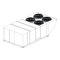
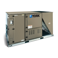
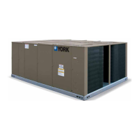
EVAPORATOR - LA300, LB180, 240, 360, 480 & 600
EACH UNIT SHALL BE:
• covered by a 1-year limited parts warranty on the com-
plete unit.
• In current production with published literature available
to check performance, limitations, specifications, power
requirements, dimensions, operation and appearance,
and equipped with a V-belt drive option that will permit
the blower RPM to be adjusted to meet the exact CFM
requirement of the system.
EACH UNIT SHALL HAVE:
• a steel angle frame to provide the rigid support required
for shipping, rigging and years of dependable operation;
• exterior panels of 18 gauge steel, finished with baked
enamel to provide a long-lasting quality appearance;
• removable panels to provide easy access to the internal
components for maintenance and service; and,
• A filter rack with 2” filters
THE DIMENSIONS OF EACH UNIT SHALL NOT EXCEED
THOSE SPECIFIED.
THE BLOWER MOTOR SHALL:
• be mounted within the insulated cabinet t minimize the
transmission of sound to the surrounding space, and
• Have a service factor of 1.15.
THE EVAPORATOR COIL SHALL:
• Consist of copper tubes arranged in staggered rows,
mechanically expanded into aluminum fins, be draw-
through, and
• include factory-mounted distributors, expansion valves
and solenoid valves for both capacity reduction and
pump down.
THE BLOWER WHEELS SHALL BE:
Dynamically balanced to minimize the levels of sound and
vibration generated by the unit.
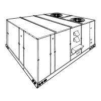
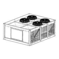
CONDENSER - LA300, LB180, 240, 360, 480 & 600
EACH UNIT SHALL BE:
• ETL and cETL approved.
• completely assembled for one-piece shipping and rig-
ging.
• leak pressure and functionally tested at the factory to
assure a trouble-free start-up after installation.
• covered by a 1-year limited parts warranty on the com-
plete unit.
EACH UNIT SHALL HAVE:
• a steel angle frame to provide the rigid support required
for shipping, rigging and years of dependable operation.
• zinc-coated steel that has been finished by a powder
paint process to provide a long-lasting, quality appear-
ance.
• removable panels for easy access to all internal compo-
nents during maintenance and service.
THE DIMENSIONS OF EACH UNIT SHALL NOT EXCEED
THOSE SPECIFIED IN THE PLANS.
EACH COMPRESSOR SHALL BE:
• mounted on isolators to minimize the transmission of
vibration.
ALL CONDENSER COILS SHALL BE:
• draw thru design.
• constructed of copper tubes arranged in staggered rows
and mechanically expanded into aluminum fins.
THE CONDENSER FAN MOTOR(S) SHALL:
• be directly connected to the condenser fans.
• have permanently lubricated ball bearings.
• have inherent overload protection.
• be three phase.
• be arranged for vertical discharge of the condenser air.
THE WIRING FOR EACH UNIT SHALL INCLUDE:
• a crankcase heater (one per compressor).
• all 24-volt temperature control circuit.
• both high and low pressure cutouts.
• Solid-state or internal line break compressor motor pro-
tection.
• Condenser fan motor control to assure stable operation
at ambient temperature down to 40 °F.
THE REFRIGERANT PIPING OF EACH SYSTEM SHALL
INCLUDE:
• a filter-drier shipped separately for field installation.
• a liquid line, moisture-indicating, sight glass shipped
separately for field installation.
• liquid line and suction line valve shipped separately for
field installation.
 Loading...