EasyManua.ls Logo

York YR User Manual

York YR
110 pages
To Next Page IconTo Next Page
To Previous Page IconTo Previous Page
Page #36 background imageLoading...
Page #36 background image
JOHNSON CONTROLS
36
FORM 160.81-O1 (1020)
ISSUE DATE 10/05/2020
SECTION 2 - OPTIVIEW™ CONTROL CENTER
Optiview Control Center
COMPRESSOR SCREEN
Overview
This screen displays a cutaway view of the chiller com-
pressor, revealing the rotary screw, and shows all con-
ditions associated with the compressor. The slide valve
positioning is animated and with the proper Access
Level it can be manually controlled. Animation of the
compressor rotors indicates whether the chiller is pres-
ently in a RUN condition. This screen also serves as a
gateway to sub-screens for calibrating the slide valve
or configuring the optional Hot Gas Bypass.
Display Only
Dierential Oil Pressure
Displays the pressure differential between the oil
pressure transducer (input to the compressor) and the
Evaporator Pressure Transducer. The displayed value
includes the offset pressure derived from auto-zeroing
during the Start Sequence Initiated. If either of the
transducers used to calculate this differential is out of
range, the display field will show XX.X.
Differential Oil Pressure = (Oil Pressure - Evaporator
Pressure) + Offset Pressure
The Offset Pressure is used to calculate the differential
pressure. The Offset Pressure is the pressure differen-
tial between the oil pressure transducer and the Evapo-
rator Pressure Transducer during the first 15 seconds of
Start Sequence Initiated. This is the transducer auto-ze-
roing. During this time the transducers will be sensing
the same pressure and their outputs should be equal.
However, due to accuracy tolerances in transducer de-
sign, differences can exist. Therefore, to compensate
for differences between transducers and assure differ-
ential pressure sensing accuracy, the Offset Pressure is
subtracted from or added to the differential pressure.
(Certain operating conditions could require the auto-
zeroing to be disabled. This must never be done by
anyone other than a qualified service technician). The
offset pressure calculation will not be performed if ei-
ther transducer is out of range. The offset value will be
taken as 0 PSI in this instance.
Discharge Pressure
Displays the pressure at the discharge of the compressor.
Discharge Temperature
Displays the temperature of the refrigerant in its gas-
eous state at discharge of the compressor as it travels
to the Oil Separator.
Discharge Superheat
In software versions C.MLM.05.04.xxx (and later),
displayed value is Discharge Temperature minus Dis-
charge Saturation Temperature. Discharge Saturation
Temperature is not a displayed value. In earlier ver-
sions, it is Discharge Temperature minus Condenser
Saturation Temperature.
FIGURE 10 - COMPRESSOR SCREEN
LD09717

Table of Contents

Other manuals for York YR

Question and Answer IconNeed help?

Do you have a question about the York YR and is the answer not in the manual?

York YR Specifications

General IconGeneral
BrandYork
ModelYR
CategoryIndustrial Equipment
LanguageEnglish

Summary

General Safety Guidelines

Safety Symbols

Explains hazard symbols used in the manual for safe operation and identification.

Document Information and Maintenance

Document Changeability

Details on how the document content may change without notice for product improvement.

Revision Notes

Records technical information and other changes made to the document.

Associated Literature

Lists related forms and documents for further system information.

Conditioned Based Maintenance

Describes a proactive maintenance program leveraging real-time data for optimal operation.

System Description and Fundamentals

System Operation Description

Explains the YORK Model YR Chiller's components and refrigeration cycle.

Capacity Control

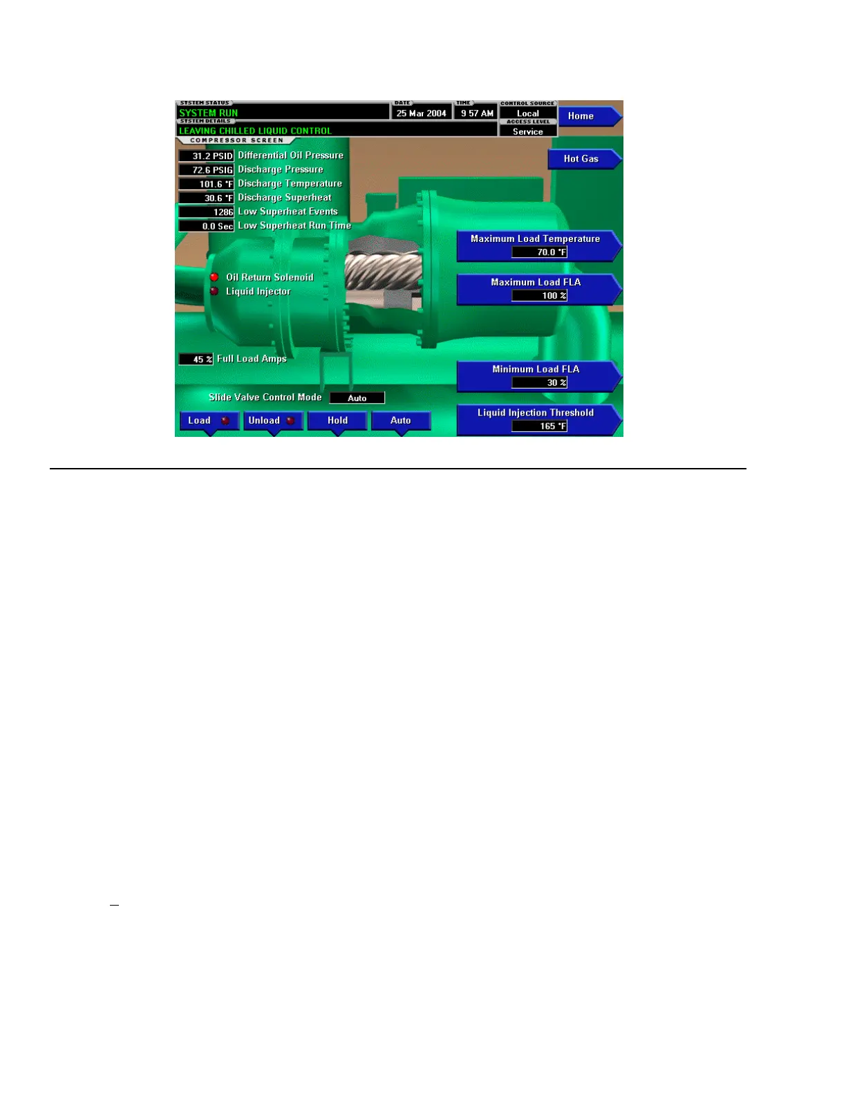
Details how the chiller manages output via slide valve for load conditions.

Chiller Operation Overview

Covers chiller start-up sequences, shutdowns, and service technician procedures.

OptiView™ Control Center Features

Control Center Introduction and Navigation

Overview of the control system, interface conventions, access levels, and navigation.

Core Chiller Screens

Details on Home, System, Evaporator, Condenser, and Compressor screens.

Specialty Screens and Controls

Covers Sensitivity, Hot Gas Bypass, Oil Separator, Starter, and Ground Fault screens.

Configuration and Setpoint Management

Screens for managing setpoints, system setup, schedules, users, and communications.

Data Logging and Reporting

Features for viewing history, security logs, trending data, and custom views.

Display Messages and Safety Shutdowns

Status and Routine Shutdowns

Describes chiller status, startup sequences, and routine shutdown causes.

Warning and Start Inhibit Messages

Alerts for conditions like clock failure, pressure limits, and startup prevention.

Safety Shutdown Faults

Details critical faults for Evaporator, Condenser, Oil, and Motor systems.

Printer Operations and Metric Conversion

Printer Reports and Types

Lists available print reports and compatible printer models (Okidata, Weigh-Tronix, Seiko).

Printer Connections and Setup

Details physical connections and configuration settings for printers.

SI Metric Conversion

Provides factors for converting English units to SI Metric values, including temperature.

Related product manuals