2. "Switch mode selective"
First step: Read out identification
Data direction Type Data packet Remarks
Vendor_ID
Send SDO 601 | 08 | 40 18 01 01 00 00 00 40
Receive SDO 581 | 08 | 42 18 01 01 DB 00 00 00 Vendor_ID 0x000000DB
Product_ID
Send SDO 601 | 08 | 40 18 01 02 00 00 00 00
Receive SDO 581 | 08 | 42 18 01 02 09 04 00 09 Product_ID 0x00000409
Revision number
Send SDO 601 | 08 | 40 18 01 03 00 00 00 00
Receive SDO 581 | 08 | 42 18 01 03 37 00 03 37 Revision number 3.55
Serial number
Send SDO 601 | 08 | 40 18 01 04 00 00 00 00
Receive SDO 581 | 08 | 42 18 01 04 54 FF 6D 06 Serial number 0x066DFF54
Second step: go to "selective mode"
Data direction Type Data packet Remarks
Send LSS 7E5 | 08 | 40 DB 00 00 00 00 00 00 00 Vendor_ID 0x000000DB
Send LSS 7E5 | 08 | 41 09 04 00 00 00 00 00 00 Product_ID 0x00000409
Send LSS 7E5 | 08 | 42 37 00 03 00 00 00 00 00 Revision number 3.55
Send LSS 7E5 | 08 | 43 54 FF 6D 06 00 00 00 00 Serial number 0x066DFF54
Receive LSS 7E4 | 08 | 44 08 00 00 00 00 00 00 00 Replies if ID is ok
Does not reply if ID is not ok
All data in the “Data packet” column are hexadecimal.
Information
If you are setting the NODE_ID using LSS, the COB_ID is set to the default values (see predefined
settings from the address switch). In other words, system-specific settings that have previously been
made must be made again.
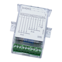
6.5 LED functions
LEDs "Run" and "Error"
The function of the LEDs is illustrated in the table "Possible LED codes."
LED "Addr / Board-Error" yellow
The address LED signals both the set CAN-OPEN address based on a binary blink code and one of
four possible board errors.
The blink code always consists of 7 bits which corresponds to 7 blinks followed by a short pause.
Long blinking corresponds to logic 1, short blinking to logic 0.
The blink code begins with the most significant bit and ends with the least significant bit.
With seven bits this corresponds to the values of 2
6
bis 2
0
.
If the values at which the corresponding bit is logic 1 are then added, you get the CAN-OPEN address
of the module as a decimal number.
The following picture describes the conversion of the binary blink code into a decimal number based
on three examples:
Operating Instructions AM-CAN-OPEN – model series Communication
L-BAL-E199-GB 1846 Index 005 Part.-No. 00163405-GB
18/28
 Loading...