4 Mechanical installation
4.1 General mounting advises
Mounting, electrical connection and commissioning are only to be performed by trained service
personnel. Adhere to all machinery-related requirements and specifications supplied by the system
manufacturer or machine builder.
CAUTION!
Attention!
When working at or in the elevator, the elevator machine and especially the brakes have to be
covered and protected against dust and chips.
Do not install distorted.
Do not apply any force (levering, bending). Above all, do not expose the rotor to any heavy
mechanical shocks.
Before starting installation, the elevator machine must be checked for transport damage, especially
the cables have to be checked.
No welding must be carried out on the elevator machine. The elevator machine must not be used as
an earthing point for welding. Magnets and bearings could be destroyed.
The cooling-airflow around the elevator machine must not be obstructed.
We rcommend keep at least 170 mm space between the brake and the wall (axial direction) to make
access to the encoder possible.
The brake design with manual hand release must be freely accessible since the levers for
brake release are moved laterally (see chapter “Start-up / manual emergency evacuation)”!
4.2 Fastening the elevator machine
On the bottom side of the socket are 4 threads.
To attach the elevator machine, use exclusively the following screw types:
4 hexagon head screws ISO 4014 - M20 - 8.8 or
4 hexagon head screws ISO 4017 - M20 - 8.8 or
4 cheese head screws ISO 4762 - M20 - 8.8
Tightening torque M20 - 8.8: 390 Nm.
Screw-in depth of fixing screws:
Minimum 30 mm
Maximum 35 mm
Fasten the screws crosswise in at least two steps to the required tightening torque.
Unevenness of the mounting surface maximum 0.3 mm.
The mounting surface has to be rigid and robust enough to withstand the forces.
For the vibration decoupling of the elevator system, damping elements should be used.
4.3 Rope fitting
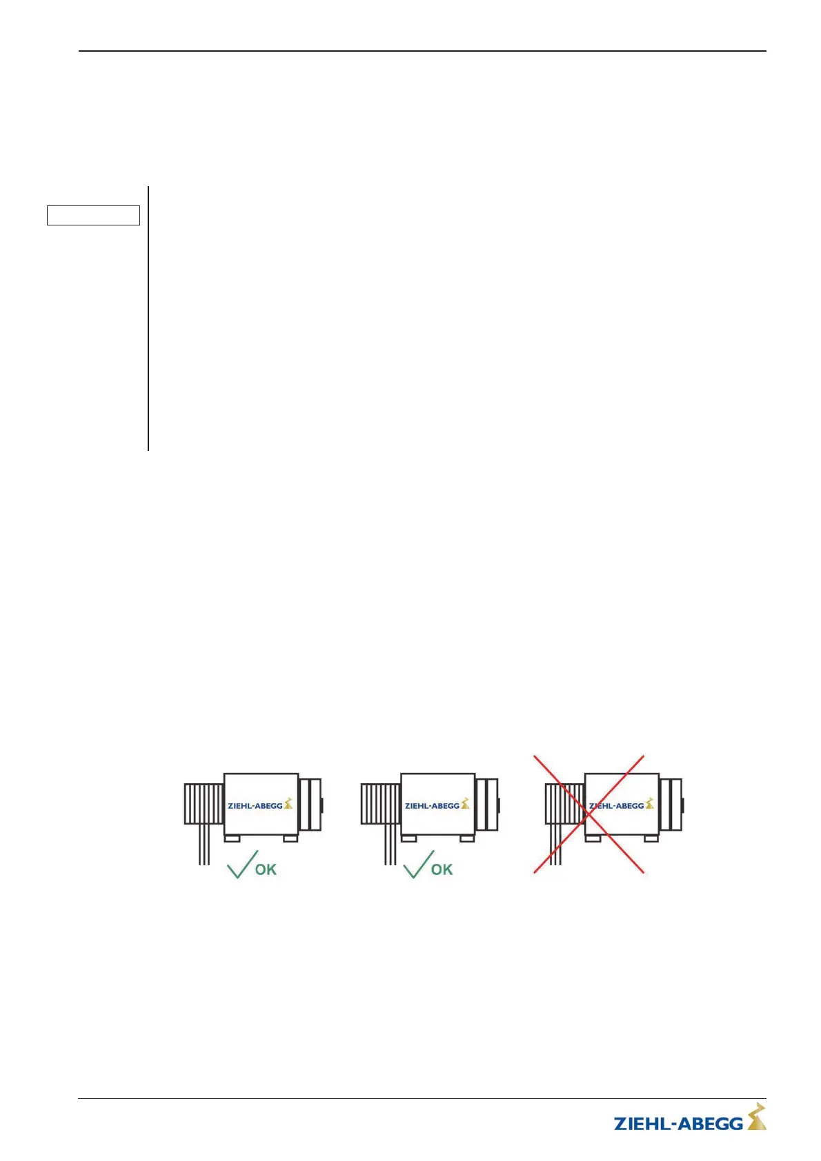
Figure 4-3-01 - Fitting the ropes
If the traction sheave should offer more grooves than the actual number of ropes, the ropes must
be applied on the sheave either centred or towards the elevator machine side.
Translation of the original operating instructions
ZAtop – model series SM200.40E/SM200.45E Mechanical installation
A-TBA21_01-GB 2021/30 Index 003 Part.-No. 01013507-GB (EU-BD 1112)
10/64
 Loading...