5.3.4 Mechanical connection conditions
Rated motor current [A] Thread size
Terminal board
Thread size
Cable gland
up to 20 M8 M25
> 20 - 35 M8 M32
> 35 - 63 M8 M40
> 63 - 80 M8 M50
> 80 - 100 M10 M50
> 100 - 125 M10 M63
> 125 M12 M63
Table 5-3-4
Permissible tightening torque for M8 bolts: 6 Nm
Permissible tightening torque for M10 bolt: 10 Nm
Permissible tightening torque for M12 bolt: 15.5 Nm
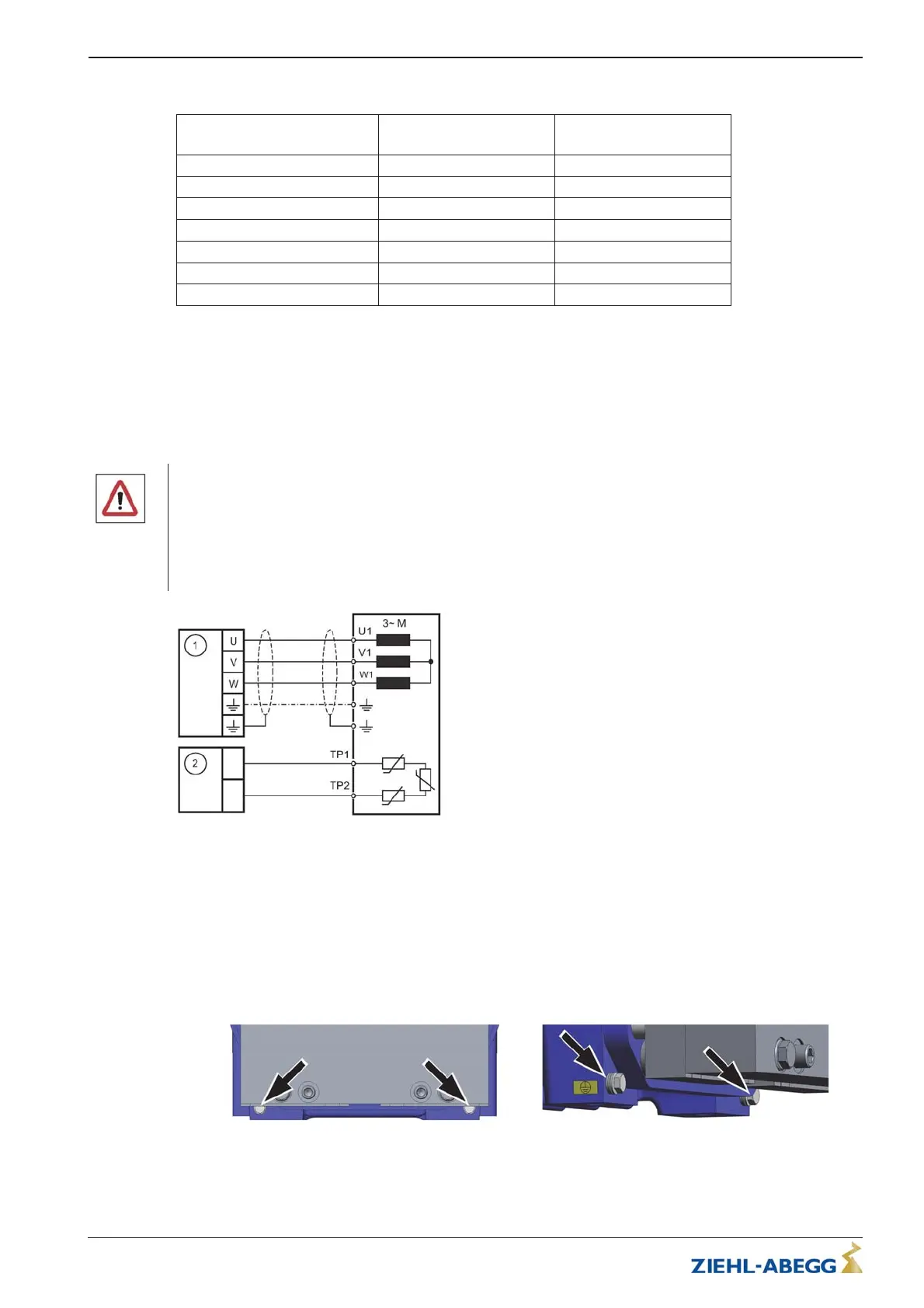
5.3.5 Connection
Danger!
The motor cable must be connected to the correct phase of the frequency inverter and the elevator
machine: U -> U / V -> V / W -> W.
If the actual direction of travel does not correspond to the selected direction, the turning direction of the
elevator machine must be changed in the frequency inverter configuration. If the motor cable is not
connected to the correct phase, control of the elevator machine is not possible. It can result in jerky
movements or uncontrolled acceleration of the elevator machine.
Figure 5-3-5-01
(1) Frequency inverter
(2) Motor temperature monitoring
5.3.6 Protective earth connection
In accordance with EN 50178 section 5.2.11 and 5.3.2.1 the protective earth connection must have a
cross-section of at least 10 mm². In the case of protective conductors < 10 mm², an additional
protective conductor must be connected. The cross-section must correspond at least to the cross-
section of the protective conductor on the connecting cable.
Hexagon head screws M6 (see arrows) are available to connect the additional protective conductor.
Figure 5-3-6-01 - Protective earth connection Figure 5-3-6-02 - Protective earth connection
When connecting the protective conductor (PE), make sure that it is connected correctly. The contact
disc (1) must be on the painted surface to ensure contact with earth.
Translation of the original operating instructions
ZAtop – model series SM200.40E/SM200.45E Electrical installation
A-TBA21_01-GB 2021/30 Index 003 Part.-No. 01013507-GB (EU-BD 1112)
15/64
 Loading...