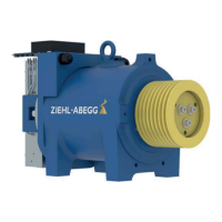
Figure 5-3-6-03 - Connecting the protective conductor
Set up the protective earth connection (PE) in the follow-
ing order (see Figure 6-3-6-03):
1 - Contact disc
2 - Washer
3 - Cable lug
4 - Hexagon head bolt
5.3.7 Temperature monitoring
•
The temperature monitoring by the PTC thermistor or temperature sensor (PT100) must be
evaluated.
•
Only connect to the inputs suitable for the relevant monitoring type.
•
Maximum permissible test voltage for PTC thermistors: 2.5 VDC.
•
When monitoring with a temperature sensor (PT100), the monitoring unit must be set to the limit
value (° C) specified in the connection diagram.
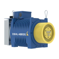
5.3.7.1 Connection diagram with PTC thermistor (PTC)
Figure 5-3-7-1-01
1 Shielding
2 1 PTC thermistor per phase
3 Attention: Do not apply any voltage > 2.5 V!
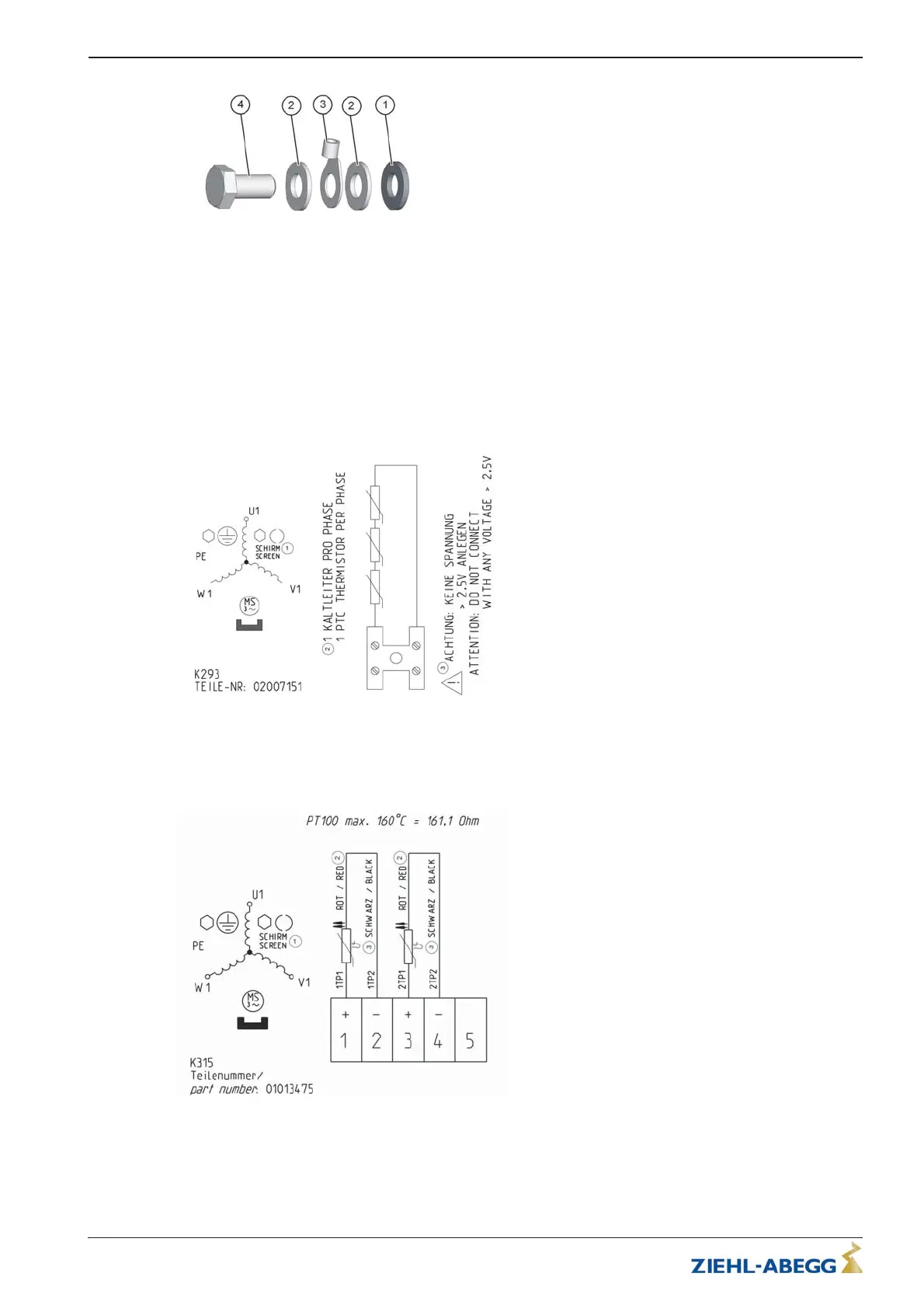
5.3.7.2 Connection diagram with temperature sensor (PT100)
Figure 5-3-7-2-01
1 Shielding
2red
3black
Translation of the original operating instructions
ZAtop – model series SM200.40E/SM200.45E Electrical installation
A-TBA21_01-GB 2021/30 Index 003 Part.-No. 01013507-GB (EU-BD 1112)
16/64
 Loading...