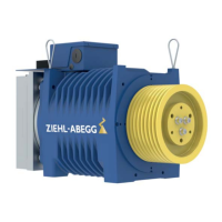
Brake wiring diagram with inductive proximity switch
Figure 5-5-6-02
(1) Brake release monitoring
(2) Brake
(3) Minimum strength 2 mA DC
(4) Operating voltage range 10 - 30 V DC
(5) Shown with currentless brake
5.6 Forced ventilation
The forced ventilation is optional and can be added afterwards.
5.6.1 Technical data
Voltage 220 - 240 [V]
Frequency 50 / 60 [Hz]
Power 20 / 19 [W]
Current 0.125 / 0.11 [A]
Table 5-6-1
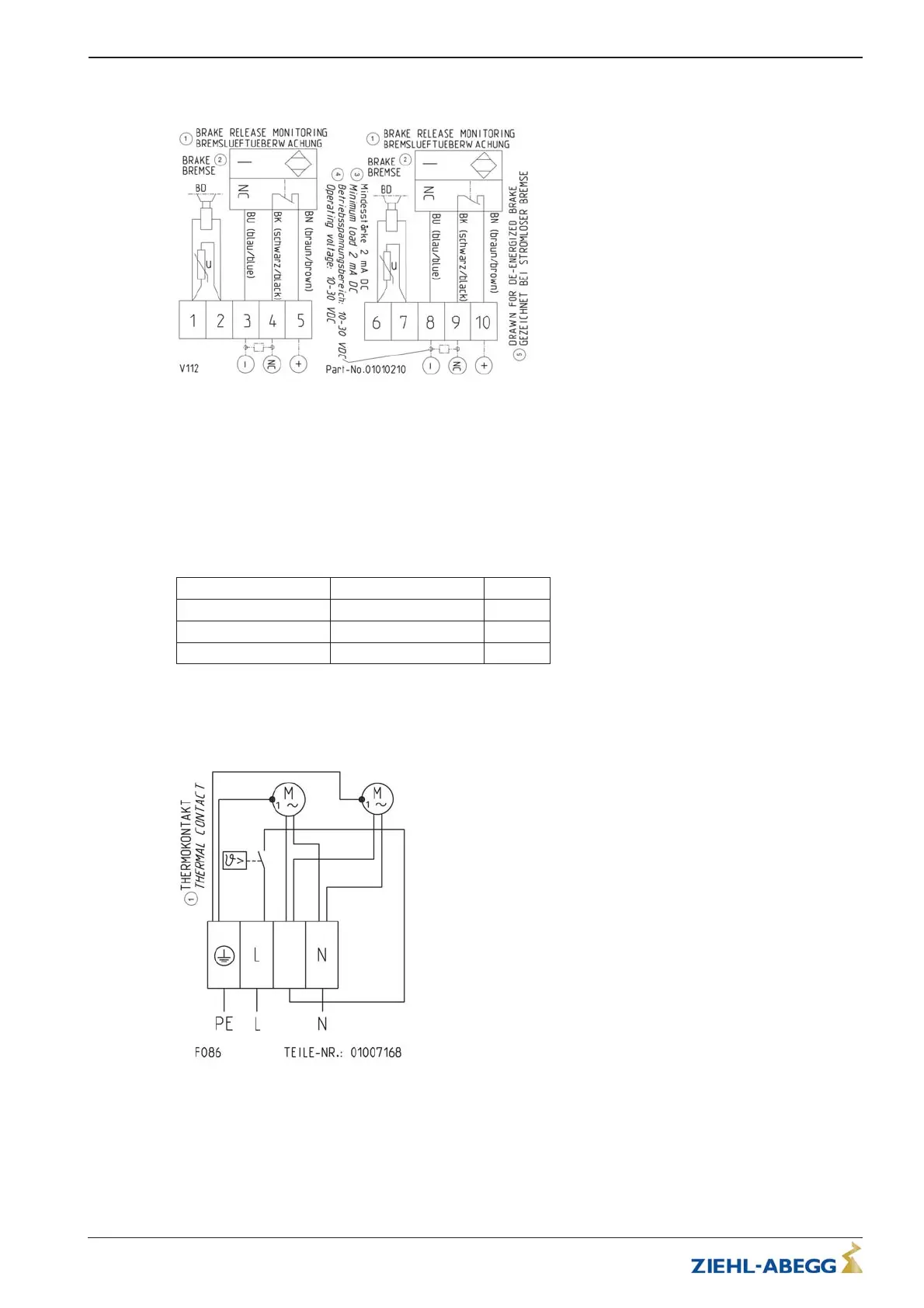
5.6.2 Connection diagram
Figure 5-6-2-01
(1) Thermal contact
Translation of the original operating instructions
ZAtop – model series SM200.40E/SM200.45E Electrical installation
A-TBA21_01-GB 2021/30 Index 003 Part.-No. 01013507-GB (EU-BD 1112)
22/64
 Loading...